


")

In our country, produce several types of indoor antennas that enable the reception of television broadcasts within the range of meter waves (1-12 th channels) at a small distance (20 km) from the transmitting station. They have a half-wave linear vibrators telescopic design or shortened loop vibrators arranged fan-shaped. Typically, such antennas are tuned to the desired channel by changing the length and position of the vibrator each time after switching the channel selector. It is very uncomfortable, and viewers often receive insufficient quality of the image.
To eliminate this drawback designed indoor TV antenna "Signal 1" to 12 " that does not require any adjustment during operation.
Only on initial installation, it must be properly placed in respect to the telecentre.
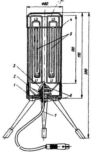
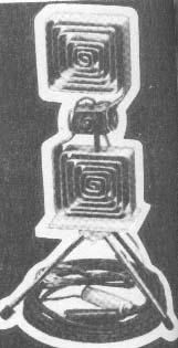
The antenna is made in the form of elektrokoteljni. A variant of the design shown in the figure in the text. In addition to the three legs on the base 1 of insulating sleeve antenna 3 (polystyrene, hard rubber, etc.) and nuts fixed spiral grid 5 and the contact wheel 2.
Grilles made from aluminum, copper or brass strip with a thickness of 2 mm, a width of 15, 20..mm and a length equal to half the length of the medium wave range (6-channel), i.e. 840 mm. Each of the gratings has three turns, the length of the scan which, from the interior, is $ 190, 260 and 390 mm. the pitch of the spiral equals 10 mm vertically and 5 mm horizontally.
The lower (in the figure) boarding the neck of the grommet, the hole left in the lattice and at the base is a square. This is done to ensure that the sleeve and grilles not arbitrarily rotated during Assembly and operation.
To connect the antenna to the TV is a coaxial cable 7 with a characteristic impedance of 75 Ohms (for example, CPT), a minimum length of 1.6 m. the Cable is passed through the sleeve and secured with a crimped spring washer 6. The ends of the cable are soldered to the terminals of the balun-matching transformer ring cores from ferrite (for TFBS). The figure for TFBS "not" shown, and the ends of the cable are soldered to the contact washers. About the production and the connection for TFBS was described in article V. Kuznetsova, V. Paramonov and A. Kukaeva "Collective television antenna" ("Radio", 1969, No. 3, pp. 26-29).
Antenna arrays close shade 4 by inserting it into the base.
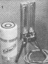
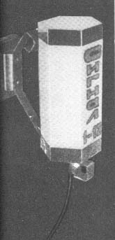
The appearance of the collected and connected to the TV antenna is shown in the 4th C. the cover. The constructive variant of the antenna with removed shade shown on the picture 1 of cover. Shown in this embodiment, the sizes of the lattices of vibrators and their location is not required.
The lattice can be made of foil on both sides stekloteks tolita. This antenna provides high-quality reception of TV shows, regardless of its location in respect to the telecentre.
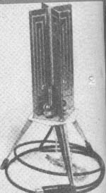
The grating can be performed to place differently, e.g., as in the photo below. The antenna is positioned so that the plane in which lie the vibrators, perpendicular to the direction of the telecentre.
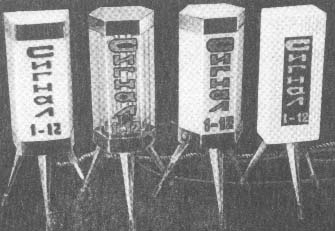
The antenna can be decorated in various ways through the use of a variety of shades. They can be run from coloured polyethylene, nylon, glass and other opaque materials with different pattern (see pictures at end of article). You can change the configuration of the base.
The antenna design accommodates both standing and hanging positions. In the second case, the legs Unscrew from the base of the antenna and screw it to the additional bracket, fixed in a convenient place.
In order for the antenna and served as a nightlight in her place 2-4 coloured lights, summing them voltage.
In the manufacture of antennas for reception in a different wavelength range or part of the channels in the range must necessarily be adjusted by changing the size of the array and determining the optimal length of the scan lanes and turns. For television at a greater distance from the telecentre is recommended to mount the antenna amplifier on a single transistor, for example GTB. The amplifier can feed from the power supply to the TV via coaxial cable similar to the amplifier, discussed in the article N. Gershenz, V. Kolomiets and N. Savenko "Antenna amplifier with remote adjustment" ("Radio", 1975, No. 4, pp. 15, 16). For controlling the operation of the amplifier on the basis of installing a light bulb connected to the ends of the coaxial cable. The hole, which is the bulb, close the cap of colored transparent plastic.
Author: W. Gurgel, Lviv; Publication: N. Bolshakov, rf.atnn.ru