


")

Before the publication, in the process of discussion among radiosportsmen, article specialist antenna technology candidate of technical Sciences K. P. Kharchenko has caused controversy. Master of sport international class, multiple winner of competitions of different levels (including Championships), gorkovchanin A. I. Grechikhin called the idea underlying the proposed design, "is very interesting and original." He also noted the simplicity of the device.
No less skilled athlete, candidate of physico-mathematical Sciences, Moscow V. N. Verkhoturov believes that the establishment of the antenna, providing the possibility of finding the minimum, "would be of great interest for athletes".
It also seems to us that this small-sized antenna can have a big advantage over the rather cumbersome "wave channel" - because often "the hunter" in search of the "Fox" has to literally Wade through dense thickets.
However, both athletes (they are joined by the master of sports of Sverdlovsk A. S. Partin) subjected to design criticism. So, they questioned the feasibility of placing the antenna on the head, the athlete is not very convenient, clarifying direction during the movement, to rotate the head (but can, apparently, produce and other search technique?). In addition, according to the rules of the competition, they say, not only vertical polarization for the antenna, but also horizontal (well, it's quite easy - just place the vibrator horizontally). In short, almost all criticisms managed to find the counter-arguments. And, most importantly, if desired, the antenna design can be changed to adapt it for carrying in hand.
More serious concerns are associated with the inevitable impact on the system parameters (in particular, symmetry) changing the capacitance relative to the ground, with a low operating height of the antenna, with its sensitivity to the reflections. .To dispel these fears can only practical operation.
The editorial Board shares the opinion of A. I. Grechina that this antenna is an "interesting proposal, which may find application to development". I hope that the article will be useful for radio Amateurs-athletes.
Hunters "Fox" should have at its disposal the equipment, allowing to distinguish the direction of "the Fox". This was the task of the antenna in conjunction with a receiver. There are two ways to build these antennas. In the first case, the antenna should •have pronounced unidirectional graph and a predetermined direction is allocated to the maximum of the received signal by comparing the signals from the neighboring areas and the choice of the title. In the second case, the antenna pattern has a single deep minimum. Here, too, the search direction is determined by comparing and selecting, but the minimum signal.
If you analyze both options, the second is theoretically preferable, though, because in the first case, to obtain a narrow beam need a "big" antenna, usually commensurate with the wavelength. In addition, to determine the direction of "the Fox" as it gets closer to her peak harder than the minimum.
In this article the option of building a small-sized antenna with a pronounced minimum in the radiation pattern. It is also proposed constructive solution of the receptor, allowing to free the hands of the athlete, that obviously will increase its maneuverability.
In order to understand the principle of operation of the antenna, refer to Fig.1,and (in the text). It shows a homogeneous segment of a long line, which includes two identical conditional generator G1 and G2 high-frequency oscillations. About mid - line, U - curve distribution of voltage along the line. If the generators are in phase, the maximum (antinode of the voltage) falls in the middle of the line. If the phase of oscillations of the generator G2 lags behind the phase of oscillation of the generator G1, the curve of distribution of line voltage will move at a certain angle j, as shown in Fig.1,b. On the contrary, if the phase of oscillations of the generator G2 is ahead of the phase of the oscillation generator of G1, it will shift the distribution curve in the opposite direction, as shown in Fig.1,b, If we agree to define the line voltage by switching at points 3-4, we can see that,|U3|> &|U1|, a, U2=0.
Fig. 1. The principle of construction of the antenna.
As discussed conventional generators can be two identical antennas, such as dipoles (Fig.1,g). Thus the phase of the oscillations in the line will depend on the direction of arrival of radio waves. In Fig.1,g arrows indicate three directions: I - radio waves coming from the antennas simultaneously; II - on the way of propagation is first antenna 1 and antenna 2; III - on the contrary, the antenna 2 front and 1 rear. Measuring the same device in the line half-wave length voltage in cross section, spaced from the antenna at a distance of 1 j in electrical degrees, will receive, respectively, all the above cases.
Thus, without knowing in advance the direction of arrival of radio waves, you can find it, rotating system consisting of two antennas as long as the unit in points 3-4 show the minimum voltage in the line. In this case, obviously, the direction of propagation coincides with the direction II. The radiation pattern of this antenna-feeder devices will be a cardioid type. Assuming that the signal is "Fox" discern the noise level of the receiver when the antenna is turned towards her at a certain angle relative to the zero direction, you can find the dead zone, inside of which is certainly one of the areas sought. As you get closer to the transmitter (with increasing levels of radiation), the dead zone will be reduced, and desired to determine the direction more accurately.
To implement the described method of constructing the antenna and receiver you can use as an example of a constructive variant, shown in Fig. 2. Here shows a General view of the device made in the form of a headset.
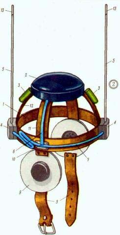
Fig.2. General view of the receptor "lisanova"
It is based on a metal Hoop 1 and arc-11 transverse and longitudinal 12. B the area of intersection of the arcs also installed metal case 2 for the receiver. If the dimensions of the battery can not be placed inside the receiver case, they are secured on the longitudinal arc 12 (two batteries - 3). Load receiver are phones 8, framed in soft, insulating strip, which is sewn straps 9 for fastening under the chin headset. Phones using strip fixed to the ends of the transverse arc 11. On the frontal and occipital parts of the Hoop 1 is placed and rigidly bonded with him the two antenna insulator 4. Antenna insulators fixed antenna 5 pin type. At the ends of the antennas are adjusting sleeve 13. The power supply terminals of the two antennas connects line 7 (line l in Fig. 1, g), line 6 connects the input of the receiver to the line 7 through the tee 10 (points 3 and 4 in Fig. 1, g). The receiver must have a high input impedance (so as not to shunt the line). Longer line segment 7 in its collapsed (zigzag) form laid on the Hoop 1.
In the manufacture of construction should strive for maximum symmetry about the vertical axis passing through the center of the Hoop. Failure to do so will entail the distortion of the symmetry in the radiation pattern and errors in determining the direction.
Fig. 3. The elements of the headset
In Fig. 3 shows the sizes of the elements that form the basis of the headset. Size S only important topics., he defines the distance in fractions of the wavelength in the line-of-7 from the frontal antenna to the connection line 6. Geometric size atogo cut line 7 is defined as
l1=S/2e ,
where e is the velocity factor. For coaxial cable with polyethylene filling e=1,51-1,52, so our options l1=70 mm. the Total length of the line is half the average wavelength taking into account the velocity of the wave in the cable. When lср=2,07 m l=680 mm.
If we add to a total length l along the same stretch of 80 mm on each side, this will increase to 150 mm l1 for more convenient placement of the tee 10 in place of a crossing arcs.
If the antenna-feeder device can be performed without any errors and strictly symmetrical electrically, the production on this it would be over.
However, it fails, and the inclusion of the line b in line 7 of the voltage signals from the antennas or not equal in amplitude or phase shift between them is not equal to 180°, when radio waves come with the "null" direction. Both does not allow to obtain a resultant voltage equal to zero. This is shown in Fig. 4. Here the vectors 1 I. 2 represent the voltage coming from the first and second antennas, respectively, the angle a is the phase shift. The resulting voltage - vector red. In Fig. 4, and the voltages 1 and 2 are equal in amplitude but not strictly anti-phase, in Fig. 4, b voltage phase, but their amplitudes are not equal to each other, in Fig. 4, a voltage of opposite phase and equal in amplitude. At all these positions, the resulting voltage is nonzero and only in Fig. 4, g it satisfies our requirements.
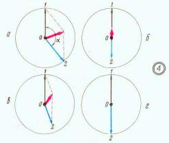
Fig.4. Vector diagram of antenna-feeder devices
To ensure both of these conditions in a real antenna-feeder device is not so easy, because when you change, for example, the length of the antenna simultaneously change the phase and amplitude coming from her signal. Still need at least one adjustment for the change only the phase (or amplitude). To ensure that only the change of phase is possible, pushing the axis of the vibrator relative to each other (changing size S), or changing the point of connection of line 6 to line 7. How can constructively change the connection point shown in Fig. 5 and 6.
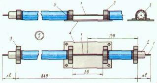
Fig.5. Sealing the ends of the cable line connector
The total length of line ( braid) is equal to 840 mm. Dl Ends, it is the same on both sides needed to be embedded in the insulators. Here 1 - center conductor cable, 2 - standout its polyethylene insulation, 3 - bracket, covering the braid and soldered to it (serves as a contact and clamp the braid). These brackets must be soldered to the Hoop headset. At a distance of 150 mm from the end bracket 3 adjacent to the frontal antenna, it is necessary to make an incision, exposing the conductor 1 during about 50 mm. the Braided cable is broken also need to plug in the bracket 3 and solder them to the copper (brass) plate 4. This incision will continue to serve as cut lines for phase compensation.
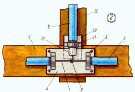
Fig.6. The method to adjust the phase of the received signal
In Fig. 6 shows the plot; the headset that is hosting the node. Here 12 - cut transverse arc, 7 - cut Hoop. Wrap and cross arc bonded with each other and have electrical contact. Plate 4 is attached to the Hoop by rivets 9, so that between it and the wrap was slit. The cable 5 is laid along the Hoop. Braid cable end of line 6 is covered by a bracket 11 fixed to the plate 10, the cable 6 is laid on the transverse arch 12 and a second end connected to the receiver. Plate 10 is securely inserted into the slit formed by the parts 4 and 7, the Central conductors 1 and 8 are connected. Standout polyethylene insulation 13 protects the conductor 8 against short-circuit with the plate 4. By moving the slit plate 10, and with it Explorer 8, you can change the switch point of the line 6, looking for the desired phase.
Setting is carried out in several techniques, the method of successive approximations. Changing the length of the vibrator of one of the antennas, trying to find the position of the enable lines to the receiver input signal was equal to zero (or had sharp low). The headset needs to be suitably focused on the transmitter. Touch the conductor lines at the time of measurement does not mean that there is no disturbance of the electrical symmetry of the system. On reaching the result you need to fix the resulting size and position. The exposed parts of the lines (cut) you need to close the lid (dielectric) and all the segments of the cables to attach the tape to the Hoop and arc.
The Hoop and the arc of the headset can be made of copper or brass tape, vibrators antennas - flexible tape or wire, insulators - from any of the high-frequency dielectric for connecting lines to use coaxial cable of almost any type. Convenient split design of the insulator. The inner half of the insulator is put on the protruding portion 2 (Fig. 5) cable after the bracket 3 will be soldered to the Hoop. The outer part of the insulator is applied on inner after vibrator antenna will be soldered to the center conductor of the line. To fasten the parts of the insulator between them is possible by means of bolts.
All metal parts of the headset must be in electrical contact, braid feeder lines is electrically shorted on the parts of the headset to which they are adjacent; braid line 6 (Fig. 2) must be soldered to the receiver housing. To comply with the electrical symmetry of the device it is desirable to lay "idle" periods of cables, exactly imitating lines 7 and 6 (Fig. 2), but on opposite sides of the headset.
To configure the antenna-feeder system is possible only outside, when the distance to the transmitter is not less than 10-15 m, in the linear portion of the characteristic of the receiver. In the area of measurement should be free of buildings and objects, which might reflect the signal transmitter and to come to the antennas from other directions. The presence of these reflections will degrade the quality settings or even make it impossible.
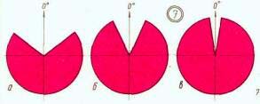
Fig.7. The radiation pattern of the antenna at different distances to "Fox"
In receivers with threshold device (the limit on a defined signal level) directivity, based on the output signal would be of the nature shown in Fig. 7, a - 7, sequentially, as we approach "the Fox".
Author: K. Kharchenko; Publication: N. Bolshakov, rf.atnn.ru