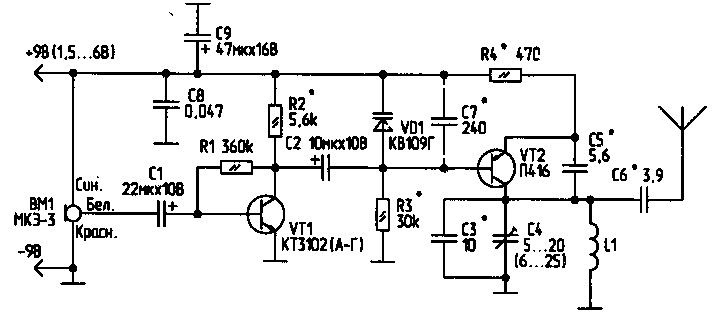
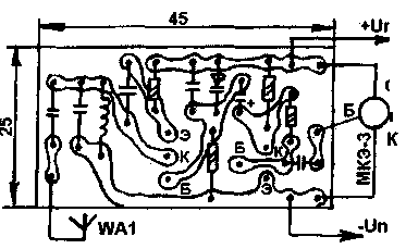
The proposed scheme is designed to listen to the conversations in the premises a short distance. The microphone is sensitive enough for reliable weak perception of sound (whisper, quiet conversation) at a distance of 3...4 m from the microphone. The range of the device is about 50 m (when the length of the transmitter antenna 30...50 cm). The scheme of the transmitter , it is desirable to reduce to a minimum size (so you cannot view it). When using the device the VA for short distances (up to 15 m) power can be reduced to 1.5...V. 3 Powering the transmitter preferably from small elements. The current consumption of the device is 3...4 mA.

The operating frequency of the transmitter — 66... 74 MHz. Coil LI consists of 6 turns of wire sew-2 0.5 mm and is wound on the frame with a diameter of 4 mm with a step of winding 1...1.5 mm. the frequency of the generator changes to VT2 slide (splitting) of turns of the coil L1.
HAM 1/98, p. 24
Since I have received many emails with questions on my article "Electronic "ear", bring for more information about configuring and improvements the scheme and drawing of the PCB.

First about setting up the transmitter. The values of capacitors C1 and C2 should be selected in the range of 4.7...33 µf to obtain the best signal quality and the maximum sensitivity and the frequency deviation. Resistors R1 and R2 should be selected within...420 330 kω and 4.7...to 9.1 kω, respectively, to obtain the best quality. Transistor VT1 should be chosen with the greatest gain current. Instead of the C4 after you configure, you can enable a permanent capacitor. If you increase the resistance of the resistor R3 will increase the frequency deviation, which increases sensitivity, but decreases the output power. The capacitor C5 is chosen in the range I. 3,3...8 pF for normal running RF generator when the voltage changes from 3 to 10 V.
And now for the improvements. If the antenna is connected directly to the collector of VT2, bypassing the C6, it will increase the power and range of operation of the device. If the varicap SW109 replace waikapu matrix SWС111 (...), using only one varicap, then slightly increase the quality of the modulation.
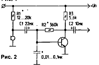
Instead of the microphone MKE-3 (VM) you can use two-pin microphones, for example from imported tape recorders or phones by including them under the scheme in figure 2.

P can be replaced by any other RF transistor, but may need to change (to pick up experimentally) the parameters of the coil L1.
(RL 2-99)
C. Owl225876, Brest region, Kobrin district, p. Orekhovsky, Lenina str., 17 — 1.


