


")

To repeat the hams offered a relatively simple antenna amplifier TV reception ranges VHF and UHF
Amplifier, schematic diagram of which is shown in Fig. 1, consists of two cascades, collected under the scheme with MA and covers a total negative chain feedback (EP) DC through a resistor R2. EP AC current in this case is negligible.
The main gain of the signal provided by the first stage. The second cascade, covered parallel (through resistor R1) and serial (via resistors R4 and R5) EP. serves to equalize the total amplitude-frequency characteristic (AFC) of the amplifier. Capacitors C4 and C5 in the emitter circuit transistor VT2 (with the meanings specified capacity) correct response in the field the lower and middle frequency bandwidth.
A feature of the amplifier is. the resistor R1 serves three functions: serves as a load transistor VT1. creates a parallel OOS transistor VT2 and together with the VT1 transistor forms a voltage divider to power the base transistor VT2. This allows a few decibels increase factor the gain compared to traditional amplifiers [1. 2] and to reduce the number applied elements.
In Fig. 2 shows the frequency response of the three amplifiers, collected under the scheme, but with various transistors: 1 CTA-2; 2 - TO-2; 3 - CTA. In the case of the use of transistors CTA in the emitter circuit of the transistor VT2 installed the resistor R4 a resistance of 390 Ohms and capacitor C4 is a capacitance of 30 pF (elements R5 and C5 are missing). Research carried out in 50 ω path the use of measuring frequency characteristics of XI-43. The standing waves (CWS) amplifiers from the entrance was in the range of 2…2.5.
Analysis of the characteristics shows that the maximum operating frequency of the amplifier reaches 0.2…0.25 from the cutoff frequency of the used transistors. Therefore, in the UHF amplifiers it is desirable to use low-power microwave transistors rated to work in the cascades, collected under the scheme with MA (two output emitter) and having the cut-off frequency over 3 GHz. Only for the MB range are suitable for high-frequency transistors a cutoff frequency of at least 1 GHz.
The amplifier is applied to the resistors MLT and capacitors K10-17. but the fit km and KD. All items must have a minimum length of conclusions.
The amplifier is collected on the Board of foiled fiberglass, the drawing of which it is shown in Fig. 3. R1 resistor soldered to the pins of the transistor VT2, placing its over it (if the transistor with plate findings).
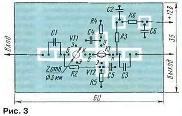
The voltage between the collector and emitter of the transistors VT1 and VT2 approximately equal to 4 V. This is achieved by the selection of resistor R2. With strong interfering signals at the input of amplifier install filters whose parameters are specified in [2. 3].
Literature
Author: N. Turkin, St. Petersburg