Decided I redo techprogram cable network, and instead of a serial connection of houses with lots of house amplifiers (powered by direct current on highways) to make 3 power amplifier (1 watt). To distribute the signal in their homes and porches was intended directional couplers. When the Soviet Union network collapsed for economic reasons (at 500 subscribers collect the fee did not cover the taxes and rental cassettes). But the descriptions of these taps, due to their extreme simplicity, may be useful to someone.
1. Tap on 3

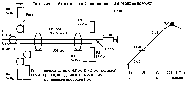
The coupler 3 is made on the basis of 220 mm piece of cable RC-150-7-31 which is removed spiral midrib. Instead proderty twisted into a bundle four solid wire in isolation. The ends of conductors loaded on resistance 75 Ohm. and their beginning (where input) connect to mains cables. Frequency response of the coupler is approximately mirrored the attenuation in the cable, which ensures the equality of the signals on the output channels of the highway.
2. Tap 2 link with maximum

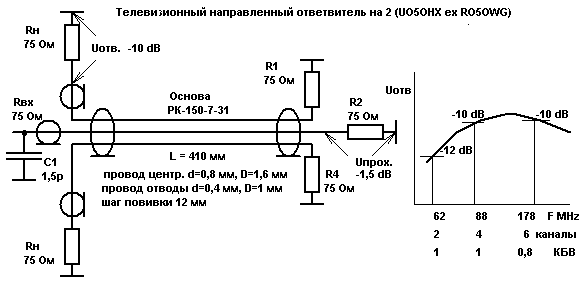
This and all subsequent taps was built with the desire to get the maximum possible output signal, used in the channels, with good IPM. Their Cestoda suitable for household distribution. Please note that the long basis increased to 410 mm.
3. Tap on 3-house
Made similarly to 2 output, but without the capacitor C1. All cores with a diameter of 0.4 mm (for insulation 1.0 mm), step irons 15 mm. U bends = -10,5 dB, U passing = is -3.5 dB (upper frequency). IPM = 1/0,84/0,75, 2/4/6 channels.4. Coupler 4-house
Made similarly to 2 output, without capacitor C1, the load center conductor 56 Ohms. All cores with a diameter of 0.4 mm (for insulation 1.0 mm), step irons 15 mm. U bends = -12 dB, U passing = -4 dB (upper frequency). IPM = 0,82/0,91/0.71 in 2/4/6 channels.
Author: E. shoustikov, UO5OHX ex RO5OWG; Publication: www.shustikov.by.ru, www.cxem.net


