For good reception of multi-program transmission telecentres working on different UHF channels, you must have a broadband directional antenna. Automatic process of the antenna are best suited to meet these requirements, which has been widely distributed. Unfortunately, the manufacture of certain kinds of automatic process antennas radio Amateurs at home is difficult.
Constructive simplicity differs variant automatic process of the antenna described in [1, 2]. According to the description, the antenna has a gain of at least 4 dB in the frequency band 470...638 MHz, i.e. allows you to receive TV channels from 21 to 41 and can be used in the near zone as an indoor antenna.

Fig.1
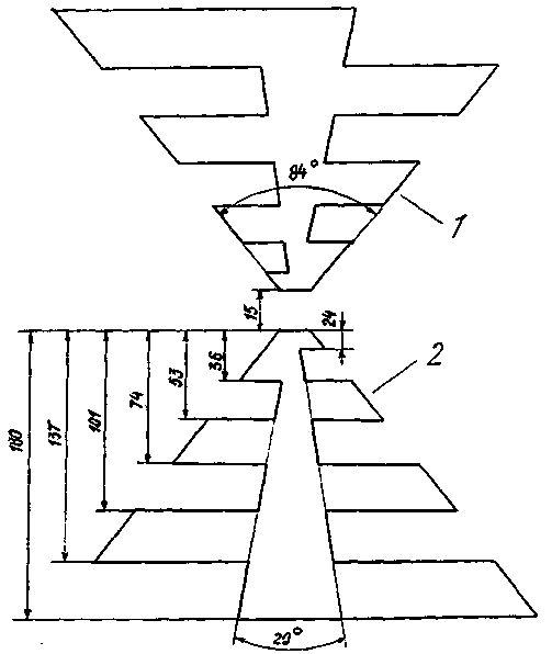
In the manufacture of multiple instances of similar antennas from sheets of aluminum having a thickness of 1.5 to 2 mm in accordance with Fig.1 and 2, and for a long period of testing them as outer, it became clear that the design has significant resistance in the most adverse climatic conditions, for example, when a considerable mass of frost and strong wind.

Fig.2
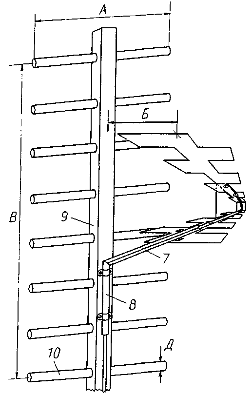
The above positive qualities of antennas and simple orchestration with electrical cord has determined the interest of the author to this design, and he tried to improve it, adding the structure of the reflector, as shown in Fig.3. In this work the antenna is improved, and moreover, it suitable for satisfactory reception of high-frequency channels meter band.

Fig.3
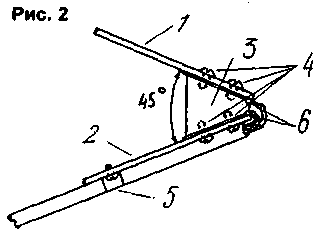
Some additional explanations to the thus obtained structure. The vibrator consists of two toothed webs 1 and 2 (Fig.1) made of sheets of aluminum having a thickness of 2 mm. In Fig.1 shows the configuration in the expanded view and the given dimensions are in millimeters. The blade is attached at an angle of 45° with respect to each other on an insulator made of organic glass 3 (Fig.2) with a thickness of 10 mm. For mounting use 4 screws with thread M3, which also must be cut in four the holes in the insulator. Cables attached to the bottom of the canvas using metal brackets 5. For connecting the cable to the paintings it is better to use special petals 6 to a thickness of 1 mm with a width and length corresponding to the size of the insulator. They can be manufactured, for example, tinplate, or other metals that allow brazing and, at the same time, compatible with duralumin. Otherwise, problems may occur additional noise and corrosion.
A vibrator is attached to a U-shaped metal profile or area 7 (Fig.3) welded to the pipe with clamps 8. The supporting mast 9 is also the basis for mounting the reflector 10. It can be made of wood, the cross section of the mast shall be not less than 30x40 mm. as elements of the reflector can be used duraluminium rods or tubes with a diameter of not less than 4 mm, While the dimensions of the reflector A=350 mm B=400 mm, preferably consist of at least 8 elements [3]. If necessary, the elements 10 are fixed with small screws.
The distance B between the reflector and the emitter is best determined experimentally, as it depends on a specific combination of channels received, it is desirable to achieve the highest quality of reception. About this distance corresponds to 0.15 L. With a smaller value may increase the antenna gain, but it will deteriorate IPM.
Literature
Author: V. Efremov; Publication: N. Bolshakov, rf.atnn.ru


