


")

The device, which is described in this article solves two problems. First, it allows one antenna to connect multiple users, and second, it gives the opportunity to take on one antenna for programs that is3 has followed passes with different polarizations.
As you know, in the same frequency band direct satellite broadcasting (Start) signals in both vertical and horizontal polarization. They can be taken on one antenna sub orthomodular converters with separate outputs vertical and horizontal polarization.
Such a device can independently produce two simple converters with rectangular waveguide, the cost of which in the CIS markets currently 3…5 dollars.
Oremodules splitter consists of three parts: the input circular waveguide section waveguide-coaxial transitions and two rectangular waveguides section with flanges for connection of vertical and horizontal converters polarizations. In the input waveguide (Fig. 1) circular cross section with diameter 19 mm installed probes placed at an angle of 90o relative to each other.
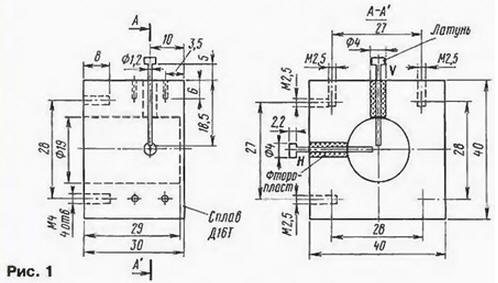
Falling wave vertical or horizontal polarization, getting in a round waveguide section, leads to the immersion of the probe EMF, which is the coaxial line is transmitted to the emitting part of the probe, made in the form cylinder 4 mm in diameter, soldered to the end of the pin probe. Immersion probe V (for signals of vertical polarization) installed at a distance of 9 mm from end the round wall of the waveguide and is arranged parallel to power lines the electric field of the incident electromagnetic wave with vertical polarization, as a result, there is induced EMF. Relative to waves with horizontal polarization V pin is perpendicular to the electric lines of force fields and EMF focusing on it.
For submersible probe H (i.e., signals of horizontal polarization) is observed reverse pattern of the electromagnetic field: it is the induced electromotive force only from the waves with horizontal polarization. Thus, it will split into two coupled waves with vertical and horizontal polarizations.
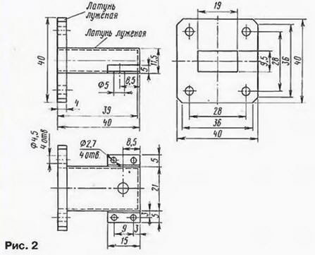
The radiating portion of the probes are located inside two rectangular waveguides (Fig. 2), attached with screws M2,5 to the side edges of the round waveguide.
And one of waveguides is bent at an angle of 90 ' in accordance with Fig. 3.
Emitting part probes installed at a distance of 7.5 mm from the end wall of the rectangular waveguides. Thus, the radiation of electromagnetic waves in N10 a rectangular waveguide. To better align with the rectangular waveguide and increasing the bandwidth koaksialinngang transition emitting part the probe is coaxial with matching transformer resistances in the form brass cylinder with a diameter of 4 mm and a length of 2.2 mm and soldered to the end of the pin submersible probe.
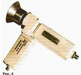
To the assembled waveguide connected to two converters start of the range 10,9… 11.7 GHz (10,7…12.05 GHz) rectangular waveguide dimensions 9.5 x 19 mm. External view of the assembled orthomodular Converter with independent outputs vertical and horizontal polarizations is shown in Fig. 4.
To connect such Converter to the antenna can be used in feeds for Prime focus or offset antennas, similar to that shown in Fig. 6 and 7 in the article "Converter STV" ("Radio", 1999, № 3, p. 8; No. 4, p.14).
To reduce the noise factor of the converters in their amplifiers microwave transistors the input stages have been replaced by transistors ATF36077 manufactured by Hewlett-Packard. It is possible to achieve a noise figure of about 0.7 dB when using converters with an initial noise ratio of 1.1…1.5 dB.
Mounted on the antenna oremodules Converter (Fig. 5) with the outputs V and H polarization (A1, A2) coaxial cables RK75-4 is connected to the dividers power (A3, A4).
As power dividers on three channels used transformer dividers ALDA 1…1250 MHz (A3, A4) used for dividing power in the UHF range. Measurements have shown that when using these divisors in the range of 0.9-1.8 GHz the reflection coefficient of the input divisors does not exceed 0.3, which is considered quite acceptable for systems start.
Outputs 1, 2 and 3 power dividers A3 and A4 connect coaxial cable RK75-4 to the inputs of the switches from the start (A5, A6, A7). The circuit of the switch (all three identical) is shown in Fig. 6. Switching the input signals H and V polarizations that are connected to the connectors XW1, XW2, switching is carried out voltage converters 13 to 18 V. When applying for XW3 connector the voltage +13 V Zener diodes VD1 and VD2 are closed and the voltage drop across the resistor R1 is zero. Transistors VT1 and VT2 are thus closed, and the voltage on the entrance XW1 is zero.
Switching diode VD6 closed and the incident wave with the entrance XW1 output XW3 not arrives. Since the transistor VT3 is also closed, the transistors VT4 and VT5 are open and with the collector of the transistor VT5 via the protective diode VD4 +12 V voltage is supplied connector XW2 power Converter vertical polarization. Diode VD5 while opens and the signal of intermediate frequency (if) output of the Converter V polarization through the capacitor C2 and open diode VD5 is supplied to the connector and XW3 further to the input of the tuner STV. When switching the supply voltage +18 V Zener diodes VD1 and VD2 are opened and the resistor R1 appears a voltage of +3 V. Transistors VT1, VT2 and VT3 open a VT4 and VT5 are closed. The input XW1 receives a voltage of +17 In the power Converter H polarization. Switching diode VD5 is closed and the diode VD6 open, and the if signal Converter, polarization N through the capacitor C1 and the diode VD6 output XW3 and further to the input of the tuner STV.
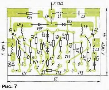
Device switching frequencies of the converters V and H polarizations is made on PCB from one-sided foil fiberglass with a thickness of 1.5 mm (Fig. 7) and placed in a metal screen made of tinned brass, on the side the wall is fixed connectors XW1, XW2, XW3 type F75 to connect tuner and power dividers A3, A4. Inductors L1 - L5 represent frameless coil with an inner diameter of 2 mm, is wound pigtail PEL 0.15 to 80 mm long. Capacitors C1 and C2 - type CD, C3 - type km-5, km-6. Resistors - MLT-0,125. In addition to these types of transistors can be applied the following: instead CTM - CTB, CTB; instead CBM and KVM - CTA, CTB, KTV, CTA, CTB, KTV, CTA, CTB; instead of diodes KDA applicable KDA or CAA. Two Zener CSA completely interchangeable one Zener diode CSA in the glass body.
Establishing orthomodular the splitter is to select the length submersible parts probes koaksialkablets transitions. In Fig. 1 shows the maximum length pins. When you change the pins are immersed in a round waveguide, gradually are shortened by 0.5…1 mm to obtain the best image quality at the channel with the lowest signal level.
Configuring a switch (Fig. 6) is reduced to the selection of Zener diodes VD1, VD2, to the switching threshold of the comparator was 15 V.
Author: V. Zhuk, Minsk, Belarus