


")

The figure shows TV antenna protruding from the roof ridge pipe-mast (total pipe length - 2 m) and metallic streamers attached to the roof. Since the antenna can satisfactorily receive signals coming from any direction, it can be used, if the desired signal is large enough and the noise level is relatively low.
The antenna resembles an overturned milk carton ("Tetra"): from the top of the mast is a solid equilateral triangle DAB, mounted on a metal mast at point a (the plane perpendicular to the mast). The length of each side of the triangle is 500 mm. the Side BD of the triangle is broken, this is where the cable is connected. Elements of ED and EB must have electrical contact with the point E and the triangle at points D and B; if necessary, they can be run from a wire with a diameter of 3…5 mm, bending the triangle DUB to the mast in the manufacturing process; then, having straightened up, he will pull the wire elements that will provide structural rigidity.
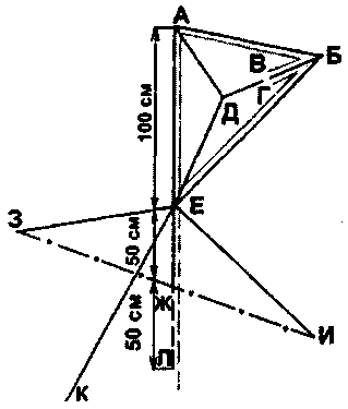
If you use "black" metals, they should be cleaned to a Shine with sandpaper and paint with a solution of bitumen in gasoline (kerosene). Electrical contacts are sealed after painting construction sealant. The need of the installation in terms of HS (20…30 mm) of the insulator depends on the rigidity of the structure.
Coaxial cable raspivaetsya Central core to the point G, braid to point b, and is fixed on the antenna brace of nylon thread or fishing line. You have two options trace cable:
- to improve image quality 1…5 TV channels - from point b to point B, then to point E and down inside the pipe;
- to improve image quality 6…60 TV channels-training In to point B, then to point a and to point E, then down inside the pipe.
If the antenna will be used only for operation at UHF, it is recommended to reduce the sides of the triangle DUB to 400 mm.
Stretch marks UOM, E3, EC have a length of 1.3±0.2 m. They should be considered as part of the antenna. The number of stretch marks and their position is chosen for the best image on all channels. On the balcony of the mast is attached to the fence without stretch marks.
You can try to change the route of the cable symmetrically depicted in the figure. But the braid must be connected to the point g and the core of the wire is on point B. this can be Achieved either by soldering cables or disassembling the antenna and turning the triangle DUB (if the Assembly was not applied welding). Welding is to make the antenna slightly modified construction. You should remove the section of the mast AE; it will take the plane of triangle DEB, and the plane of the triangle DUB will be perpendicular to the plane of DEB and the mast EWL (it is like a child's "slingshot"). If necessary, you can install an antenna amplifier at point E (or L).
Author: N. Gorovoy, Smolensk; Publication: N. Bolshakov, rf.atnn.ru