Active antenna (actually a combination of antenna and amplifier) have already been described on the pages of the magazine. However, the difficulties of reception of television programs in bands VHF and UHF forced to return to this subject. In placed here the article is interesting, in our view, a variant of the design of the antenna and combo amp MB-UHF.
The problem of high-quality reception of TV programs always concerned viewers. And today she not only has not lost its relevance, and became even more important and complex. First, increased the number of television programmes, primarily commercial, which often lead through transmitters small capacity. Secondly, broadcasters have begun to actively explore the UHF range. And thirdly, the increased number of devices - consumers TV signal (usually in a family there are two TVs and more, and then the VCR). Therefore there is a need to install a UHF antenna, summation of signals VHF and UHF for transmission to consumers via a single cable and dividing the television signal between all consumers. The last operation is not without losses, and if the signal level is small, it leads to the deterioration of the reception. There are cases when the antenna, served more than one year, no longer provides the required quality. Installation is the same for each consumer my antenna is quite troublesome.
The way to deal with this situation is to install the combined one active antenna MB-UHF. In the General case, it consists of actually two antennas MB and and UHF amplifier module that amplifies the signals from each of them, summarizes and conveys to consumers via a single cable reducing. Module feature in the direct vicinity of the antenna and feed cable. Thanks to this build the signals from the antennas with virtually no loss comes to amplifying module that improves the overall ratio signal/noise, and a high level signal in the cable reduction allows you to connect to the antenna a few loads without fear to degrade image quality.
A schematic diagram of the amplifying module depicted in Fig. 1. It contains two independent channels of amplification. The signal from the antenna MB Vit-phase interference. At the entrance of the cascade set of coils L1, L2, eliminating the accumulation charges of static electricity on some antennas and diodes VD1 - VD4, protecting the amplifier from lightning. Transistor VT5 is assembled additional amplifying cascade. The transmission coefficient of the channel is equal to 15...20 dB.
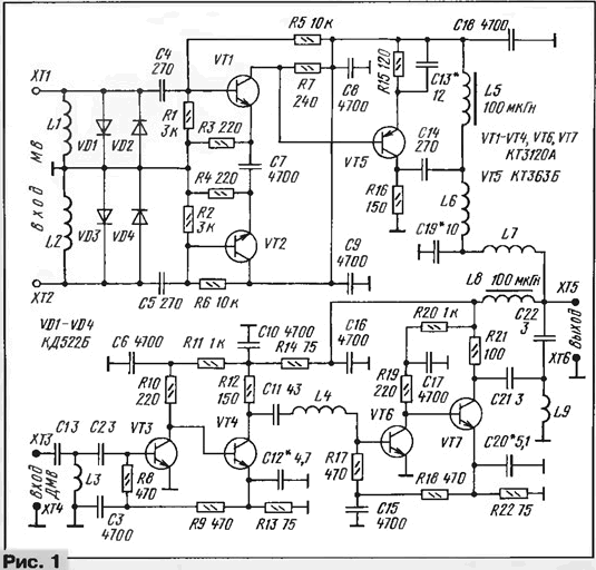
Signals MB pass the cables through the low pass filter L6C19L7 with cutoff frequency 250 MHz. Through the same filter and the throttle L5 per channel supply comes voltage to reduce cable. In addition, the filter does not transmit UHF signals.
Channel gain UHF consists of two series-connected similar the amplification stage. The first one is assembled on transistors VT3, VT4 scheme with galvanic coupling, thereby automatically on exit the operating mode selected and the maintenance of temperature and supply voltage. At the entrance of the cascade filter is installed HF C1L3C2 with a cutoff frequency of 450 MHz, which suppresses low frequency signals and noise. Similar to the high pass filter C21L9C22 at the output of the second cascade passes the UHF signals and does not transmit signals MB. Consequently, the filters at the outputs of the channels are mutually untie them.
Coil L4 provides the coordination between the stages of channel UHF and correction the total response. The total channel gain is equal to 32...36 dB that allows you to transfer signals in this range using long cable for a few consumers. Channel UHF is fed through the inductor L8 with reduce cable.
The amplifying module is assembled on a printed circuit Board from bilateral foil fiberglass. A sketch is presented in Fig. 2. All items posted with the printed conductors. The second side metallized and left plays the role of the screen (below the horizontal dashed lines in Fig. 2). On the circuit Board soldered to it strips of copper foil connecting it with the General the wire of the first party. Contacts HT - HT made in the form of racks of segments copper wire of diameter 1 mm, pressed into the holes of the Board. Around contact HT and HT foil on the second side of the Board is removed (shown in Fig. 2 dashed line). Through the holes a and b of the printed first side track connected to printed circuit paths of the second party, they are shown by the dashed line. In these tracks drilled holes that are required when placing the amplifying module directly from the vibrator antenna MB. With UHF antenna module connecting piece of the coaxial cable.
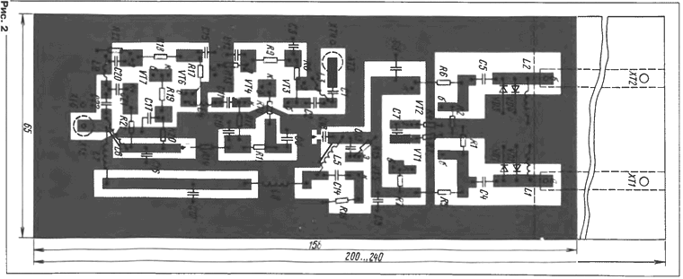
If placed too close to the antenna module must be securely protected from atmospheric influences. For this, all parts and traces cover layer electronic moistureproof lacquer (e.g. UR-231) or liquid epoxy glue, and then painted with a waterproof paint. After that, the details is desirable close the protective cover, which is made of food grade tinplate and solder on the Board outline. The soldering points of the cables, and the cables to the external protective layer and the attachment of the module to the antenna should also be moisture resistant paint paint.
In the device, except as indicated in the diagram, the permissible use of transistors CTA (VT5) and CTA (the rest). Capacitors - km, KLS, CD ROM or open frame. Resistors - MLT, S2-33, P1-4. When applied to the hull of the capacitors in the channel UHF preference should be given to the capacitors with minimum dimensions, and the length of their conclusions should not exceed 3 mm.
Coils L3, L4, L9 wound wire sew-2 0,2 mandrel with a diameter of 2 mm and contain 2.5; 4 and 2.5 turns. Inductors L5, L8 - DM-0,1 inductance 20... 100 µh. The remaining coils are wound wire sew-2 0,8 to the mandrel diameter of 4 mm. Coils L1, L2 contain 15, and L6, L7 - 4,5-loop.
The establishment of the amplifying module is reduced to the adjustment of its frequency response. Channel MB's make the selection of the capacitor C13, and channel UHF capacitors C12, C20, setting the maximum and uniform gain throughout the frequency range. The change of the coil inductance L4 (sliding or pushing the coils or changing their number) adjust frequency response in the upper part of the UHF range. If the UHF range is only one or two television channels, it makes no sense to obtain uniform gain more expedient to achieve the greatest gain the frequencies of these channels. In the MB range, it makes sense to get maximum gain at the frequency of the least powerful of the channel.
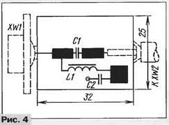
The amplifying module is fed from the power supply voltage of 12 V at a current of not less than 70 mA via adapter terminal, the circuit of which is shown in Fig. 3. The adapter include in the gap reduce cable. It is collected on a small PCB from bilateral foiled fiberglass, a sketch of which is shown in Fig. 4. On the one side it is carved only three contact pads and drilled one hole, the second left side fully metallized and serves as common wire. If the items on it to fill in with epoxy glue, then you can do without housing.
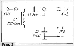
High-frequency coaxial socket XW1 (normal television) soldered in common petal to the metallized surface of the second side, and the Central petal - one print area on Fig. 4. Coaxial cable with plug at the end of the solder braid to the total metallic surface, and center conductor to the other platform in Fig. 4. The power source is connected parallel to the capacitor C2. If the sound source with adjustable in the range 6... 12 V voltage, it will be possible to smoothly adjust the gain of the module, i.e., to find its optimal value.
In addition to amplifying module, the antenna must contain and actually antenna. Here you can go different ways. If the radio is already available the MB antenna (e.g., wave channel or any other) that does not operate very well and plan to install a UHF antenna, then do so. Otpaivaete the lead-in cable from the old antenna MB and install directly on it (on active loop vibrator antenna "wave channel") of the amplification module. Install the UHF antenna and attach its cable to the module. If the reception is in the reception zone or close to its boundary, it is possible to do complex antenna as a rule, there is no need. Here fit a simple broadband antenna as MB and UHF. Below are described in more detail the design of such active antenna.
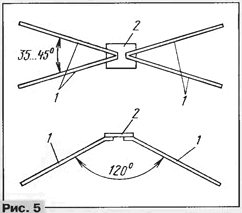
In the MB range is convenient to use the antenna "fan vibrator", which is sometimes called "butterfly". It represents (Fig. 5) cut four metal pipe or strip 1 length 108...115 cm, which is securely mounted on the dielectric plate 2. The angle between the vibrators (in vertical plane) each shoulder is in the range of 35...45°, and the shoulders of the vibrator feature at an angle of 120° in the horizontal plane, as shown in Fig. 5, which allows to eliminate the failures in the radiation pattern. Sometimes vibrators in each shoulder do different in length, for example, lower by 30...40% shorter top. Material and pipe diameter or thickness of the bands selected on the basis of obtaining mechanical strength. Too thin will not withstand the wind loads, and the use of thick will lead to considerable weight of the antenna. The most appropriate pipe diameter 6...8 mm Directly to this antenna is attached amplifying module.
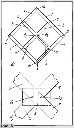
In the UHF range is convenient to use a zigzag antenna, easy to the manufacture and sufficiently broadband. Its design is presented in Fig. 6. It consists of four lanes from 1 aluminum or copper, length 300 mm, width 15...20 mm and a thickness of 1.5...2 mm, and four lanes 2 length 145...150 mm. All the bands are fastened to each other at points a by rivets or screws. Between short strips provide a gap of about 10 mm. To obtain mechanical strength between them set the plate 3 from fiberglass thickness 1,5...2 mm (Fig. 6,b) and fasten it at the points σ1 and σ2. If copper strip, need to be blanched in the attachment, and if aluminum, rivets or the screws are placed the petals, which are further soldered coaxial cable. It lay, as shown in Fig. 6,a dashed line, and the strip to the point σ2 solder braid, and σ1 is the center conductor. After mounting all the soldering joints and fasteners coated with water-resistant paint.
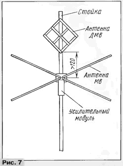
After fabrication of antennas VHF and UHF are conducting a joint Assembly. If the active antenna designed to be installed on the roof, they can be mounted on metal the pipe, as shown in Fig. 7, which is certainly then grounded. In this case the UHF antenna is attached to the pipe metal screws through a small strip in two points and the bottom and the top in Fig. 6) so that the soldering points cable does not touch the pipe. The MB antenna to which screw amplifying module (pins 1 and HT in Fig. 2), attached to the pipe also screws via dielectric plate, and so that its metal parts are not touched pipe. If the antenna is placed on a wooden rack, it must be dried well and painted with waterproof paint. However, you have to spend a tire on the ground side, free from the antennas. When installing the antenna on the balcony, loggia, outdoor the veranda requirements for mechanical strength are reduced, and grounding in these cases not necessarily. The appearance of the mounted designs shown in the photo the beginning of the article.
If you plan to use an active antenna in areas with poor reception, to be a more effective antenna. For the range of MB's that can be "wave channel", zigzag, UHF framework consisting of three frames, or "wave channel" (however it is narrowband).
Author: I. Nechaev


