The problem of creation of the transmitting antennas of interest to many hams. As you know, well radiate TX antennas, i.e. antennas whose size is comparable with wavelength. However, to create a full-sized antenna is often difficult. Therefore many are turning to shorter antennas.
When using such antennas, there is a paradoxical situation in which a low output impedance of the transistor cascade Rвых (for example, when EC=12.6 V, pout=10 W, Rвых=8 Ohms) is transformed into a high impedance cable 50 or 75 Ohms, and then again lowered to align with the low resistance of the shortened antenna. It is easier to negotiate a low output impedance (8 Ohm) cascade transistor with low resistance shortened loop antenna (in the velocity factor of 0.45 Rизл=8 Ohms). For this it is necessary to directly combine the output stage with a shortened antenna.
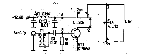
Schematic diagram of the active antenna CB-band is shown in the figure.

Amplifying cascade operates in the "C" class and can be used for amplification of H M and CW signals. The power output of the cascade is 10 watts. It is achieved at input power of 0.1...1.0 W - depending on the type of transistor. Most high gain transistors provide CTA, CTA, a lesser - CTA, CTV. For matching the input impedance with the transformer cable is used, which is made on a ferrite-PTO ring with a diameter of 10 mm with a permeability of 400. The coil consists of 10 turns of two twisted wire PEV-2 in diameter at 0.31 mm.
The output of the amplification stage included a shortened loop antenna having sizes 1,3x1,3 m and is made of a copper bus-section 3x5 mm Amplifier is included in the gap of the middle of one of the vertical sides, providing work antenna with vertical polarization. To reduce the resonant frequency at point 3, 4 included shortening capacity C4, which must have sufficient mechanical strength (for example a capacitor with air dielectric).
Wires connecting the frame with the transistor must have a minimum length of 1...2 cm).
For AM and SSB between points A and b is switched resistor 500...600 Ω, which sets the quiescent current of 50 mA. It should be noted that in this case the temperature stability of the cascade will be low, and it can only be used indoors.
The transistor must be provided with a radiator, an area not less than 500 cm2. Choke DR1 - type DPM is 2.4.
To power the active antenna you can use a separate wire, but it is particularly convenient to fuel her input on a coaxial cable with the dividing capacitors and chokes. The allowable current density for the Central wire of the cable is 3 A/mm2, which allows the use of any cables except the slim.
Active antenna may be mounted in the window opening or on the balcony.
Initial setup of the antenna can be implemented using GSS, weakly associated with the antenna (for example using a small frame), and a performance indicator of field strength. Then set voltage (50% of nominal) and served the excitation voltage for the transistor. A change in the magnitude shortening capacity to achieve resonance, which is manifested in the increase of the collector current and the increase in meter readings of the field strength. After that, as you move the point 2 on the side of the frame to achieve a further increase of the indicator of tension, periodically adjusting C4. Then the voltage is brought up to par.
Setting can also be run with the help of measuring frequency characteristics, enabling the output ICH the input of the active antenna, and the entrance ICH connecting with a small frame, weakly associated with active loop antenna. It is advisable to check the SWR of the input circuit, which should be close to 1.
Literature
Author: M. Animov (RU3PF, ex UA3POC); Publication: N. Bolshakov, rf.atnn.ru


