


")

This nifty sound level meter is a perfect one chip replacement for the standard analog meters. It is completely solid state and will never wear out. The whole circuit is based on the LM3915 audio level IC and uses only a few external components.
Circuit diagram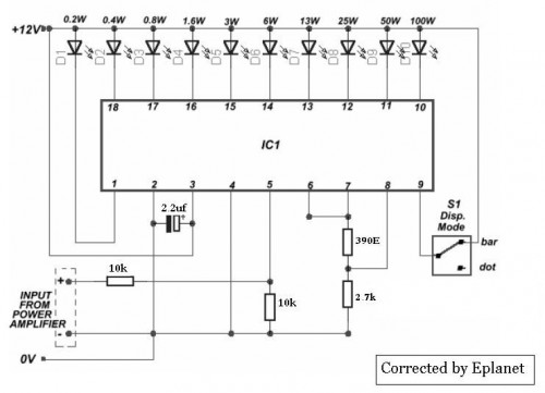
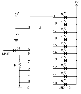 Parts
Parts
- C1 2.2uF 25V Electrolytic Capacitor
- R1 1K 1/4W Resistor
- D1 1N4002 Silicon Diode
- LED1-LED10 Standard LED or LED Array
- U1 LM3915 Audio Level IC
- MISC Board, Wire, Socket For U1
- V+ can be anywhere from 3V to 20V.
- The input is designed for standard audio line voltage (1V P-P) and has a maximum input voltage of 1.3V.
- Pin 9 can be disconnected from ground to make the circuit use a moving dot display instead of a bar graph display.