


")

The following scheme diagram is the four 4 band equalizer circuit. Equalizer device is generally used to improve the fidelity of sound, to emphasize certain instruments, to remove undesired noises, or to create completely new and different timbres.
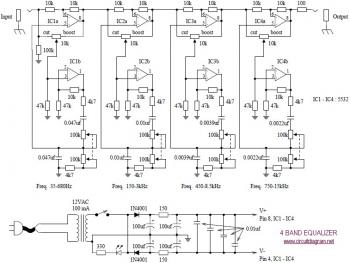
This circuit operated with 12VDC symmetrical / dual polarity power supply. Power supply circuit provided on above diagram. For better power supply output and of course will improve the audio performance, you may use IC regulator LM7812 and LM7815.
The equalizer uses four pieces of variable resistor to cut and boost four range of audio frequency, that are:
- Low frequency: Freq. 35-680Hz
- Medium frequency: Freq. 150-3kHz
- Medium/semi high frequency: Freq. 450-8.5kHz
- High audio frequency: Freq. 750-15kHz
Download 4 Band Equalizer circuit in PDF document from below link:
 4 Band Equalizer Circuit 14.60 KB
Download Circuit Diagram
4 Band Equalizer Circuit 14.60 KB
Download Circuit Diagram