


")

This is high fidelity, high quality audio amplifier circuit diagram. You don’t need pre amplifier circuit for this design.
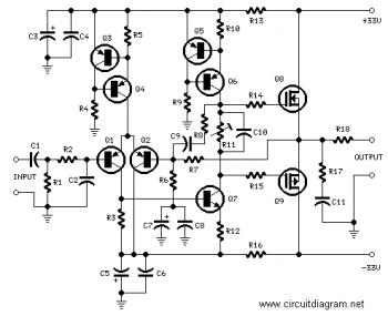
Component list:
R1,R4 = 47K 1/4W Resistors R2 = 4K7 1/4W Resistors R3 = 1K5 1/4W Resistors R5 = 390R 1/4W Resistors R6 = 470R 1/4W Resistors R7 = 33K 1/4W Resistors R8 = 150K 1/4W Resistors R9 = 15K 1/4W Resistors R10 = 27R 1/4W Resistors R11 = 500R 1/2W Trimmer Cermet R12,R13,R16 = 10R 1/4W Resistors R14,R15 = 220R 1/4W Resistors R17 = 8R2 2W Resistor R18 = R22 4W Resistor (wirewound) C1 = 470nF 63V Polyester Capacitor C2 = 330pF 63V Polystyrene Capacitor C3,C5 = 470?F 63V Electrolytic Capacitors C4,C6,C8,C11 = 100nF 63V Polyester Capacitors C7 = 100?F 25V Electrolytic Capacitor C9 = 10pF 63V Polystyrene Capacitor C10 = 1?F 63V Polyester Capacitor Q1-Q5 = BC560C 45V100mA Low noise High gain PNP Transistors Q6 = BD140 80V 1.5A PNP Transistor Q7 = BD139 80V 1.5A NPN Transistor Q8 = IRF532 100V 12A N-Channel Hexfet Transistor Q9 = IRF9532 100V 10A P-Channel Hexfet TransistorUse this power supply circuit to handle the amplifier.
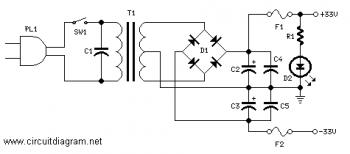
Component list:
R1 = 3K3 1/2W Resistor C1 = 10nF 1000V Polyester Capacitor C2,C3 = 4700?F 50V Electrolytic Capacitors C4,C5 = 100nF 63V Polyester Capacitors D1 200V 8A Diode bridge D2 5mm. Red LED F1,F2 3.15A Fuses with sockets T1 220V Primary, 25 + 25V Secondary 120VA Mains transformer PL1 Male Mains plug SW1 SPST Mains switchCircuit Notes:
- Can be directly connected to CD players, tuners and tape recorders. Simply add a 10K Log potentiometer (dual gang for stereo) and a switch to cope with the various sources you need.
- Q6 & Q7 must have a small U-shaped heatsink.
- Q8 & Q9 must be mounted on heatsink.
- Adjust R11 to set quiescent current at 100mA (best measured with an Avo-meter in series with Q8 Drain) with no input signal.
- A correct grounding is very important to eliminate hum and ground loops. Connect in the same point the ground sides of R1, R4, R9, C3 to C8. Connect C11 at output ground. Then connect separately the input and output grounds at power supply ground.
Technical data:
- Output power: well in excess of 25Watt RMS @ 8 Ohm (1KHz sinewave)
- Sensitivity: 200mV input for 25W output
- Frequency response: 30Hz to 20KHz -1dB
- Total harmonic distortion @ 1KHz: 0.1W 0.014% 1W 0.006% 10W 0.006% 20W 0.007% 25W 0.01%
- Total harmonic distortion @10KHz: 0.1W 0.024% 1W 0.016% 10W 0.02% 20W 0.045% 25W 0.07%
- Unconditionally stable on capacitive loads