


")

Here the 100W RMS Amplifier schematic diagram:
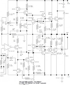
This circuit is quite simple but will give you high quality audio output. Take a note that above diagram designed for single input and single output (mono system). For stereo system, you need to build two similar circuits.
The input stage is an LF351 op amp which provides most of the open loop gain as well as stabilizes the quiescent dc voltage. This feeds a level shift stage which references the voltage swing to the (-) rail. The transconductance stage is a darlington, to improve high-frerqency linearity. The 2SC2344 by itself has a rather large collector-base capacitance which is voltage dependent. The MPSA42 presents this with a low-z and has a C(ob) of only a few pf that is effectively swamped by the 33pF pole-splitting cap. The stage is supplied by the 2SA1011 active load (current source) which is about 20 ma. The current to the stage is limited by the 2N3094 to about 70 ma under worst case.
The output is a full complementary darlington with paralleled outputs. Although you could “get away with” only one if only 8 ohm easy-to-drive loads are used, this is not recommended. The use of parallel devices increases the ability to drive reactive loads (which can pull a significant current while the voltage waveform crosses zero and puts a high voltage and a high curent across the transistor simultaneously), gives the amp a higher damping factor, and reduces the maximum current each transistor has to supply to peaks (remember, the gain of a power transistor drops as the current increases).
Compensation is two-pole and one zero. The op-amp’s pole and the pole generated by the 33pf cap and the 470 ohm bias resistor of the MPSA42 dominate. (the 33pF gets multiplied by the stage gain.) The 22 pf feedback capacitor provides lead compensation, and is taken from the output of the tranconductance stage rather than the output itself. In this way, the phase lag introduced by the output transistors is not seen by the high-frequency feedback. This intorduces a closed-loop pole which limits the high-frequency response. The two compensation capacitors must be type 1 creamic (NPO) or silver mica — with ZERO voltage coefficient.
The amplifier circuit was designed to run 2 channels off a +/- 55 volt unregulated supply, reducing to +/- 48 volts under full load. It used a 40-0-40 volt, 5 amp toroid transformer, a bridge rectifier, and 10,000 uf of filter cap per side. If a standard EI transformer is used, a 6-amp rated unit should be used. With this power supply, it produces 100 watts continuous, both channels driven into 8 ohms resistive with no clipping. Dynamic headroom is about a db and a half. For more headroom, unloaded voltages to +/- 62 volts can be used with no circuit modification.
Read detail explanation about this 100W RMS audio amplifier HERE
Download large schematic diagram in PDF format HERE