


")

This is the circuit diagram of 18W audio amplifier. The circuit is quite simple and inexpensive to built. It uses a pair of power transistor TIP41A and TIP42A for single channel operation. The power supply used for this circuit is dual polarity (splitted) power supply, use center tap transformer to build this kind of power supply.
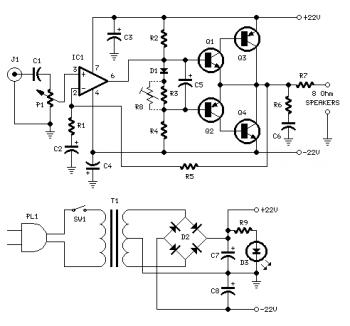
18W Audio Amplifier Circuit Diagram
Parts list:
P1 = 22K Log.Potentiometer (Dual-gang for stereo) R1 = 1K 1/4W Resistor R2 = 4K7 1/4W Resistor R3 = 100R 1/4W Resistor R4 = 4K7 1/4W Resistor R5 = 82K 1/4W Resistor R6 = 10R 1/2W Resistor R7 = R22 4W Resistor (wirewound) R8 = 1K 1/2W Trimmer Cermet (optional) C1 = 470nF 63V Polyester Capacitor C2,C5 = 100?F 3V Tantalum bead Capacitors C3,C4 = 470?F 25V Electrolytic Capacitors C6 = 100nF 63V Polyester Capacitor D1 = 1N4148 75V 150mA Diode IC1 = TLE2141C Low noise,high voltage,high slew-rate Op-amp Q1 = BC182 50V 100mA NPN Transistor Q2 = BC212 50V 100mA PNP Transistor Q3 = TIP42A 60V 6A PNP Transistor Q4 = TIP41A 60V 6A NPN Transistor J1 RCA audio input socketPower supply parts:
R9 = 2K2 1/4W Resistor C7,C8 = 4700?F 25V Electrolytic Capacitors D2 100V 4A Diode bridge D3 5mm. Red LED T1 220V Primary, 15 + 15V Secondary 50VA Mains transformer PL1 Male Mains plug SW1 SPST Mains switc18W Audio Amplifier Circuit Notes:
- Can be directly connected to CD players, tuners and tape recorders.
- Don’t exceed 23 + 23V supply.
- Q3 and Q4 must be mounted on heatsink.
- D1 must be in thermal contact with Q1.
- Quiescent current (best measured with an Avo-meter in series with Q3 Emitter) is not critical.
- Adjust R3 to read a current between 20 to 30 mA with no input signal.
- To facilitate current setting add R8 (optional).
- A correct grounding is very important to eliminate hum and ground loops. Connect in the same point the ground sides of J1, P1, C2, C3 &C4. Connect C6 at the output ground.
- Then connect separately the input and output grounds at the power supply ground.