This circuit consists of six square wave oscillators. Square waves are made up of a large number of harmonics. If six square waves with different frequencies are added together, the result will be a signal with a very large number of frequencies. When you listen to the result you’ll find that it is very similar to a steam whistle. The circuit should be useful in modelling or even in a sound studio. This circuit uses only two ICs. The first IC, a 40106, contains six Schmitt triggers, which are all configured as oscillators. Different frequencies are generated by the use of different feedback resistors.
Circuit diagram:
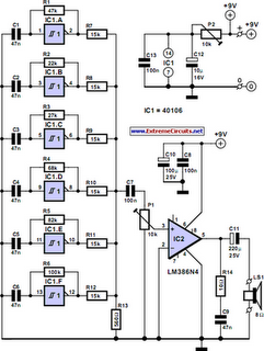
Steam Whistle Circuit Diagram
The output signals from the Schmitt triggers are mixed via resistors. The resulting signal is amplified by IC2, an LM386. This IC can deliver about 1 W of audio power, which should be sufficient for most applications. If you leave out R13 and all components after P1, the output can then be connected to a more powerful amplifier. In this way a truly deafening steam whistle can be created. The ‘frequency’ of the signal can be adjusted with P2, and P1 controls the volume.
Author: Gert Baars - Copyright: Elektor Electronics 2004


")
