Found that the battery is more reliable and longer if the controller's electrical system supports on-Board voltage, changing to a certain temperature. Serial same automotive instrument that can not provide.
Author of published articles managed by simple means to get close to the optimal temperature coefficient of the on-Board voltage.
The disadvantage of the domestic automotive electronic voltage stabilizers, specifically, commercially available A and A. is that they do not provide the necessary temperature dependence of the on-Board voltage [1; 2].
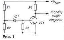
In Fig. 1 shows a typical circuit threshold traditionally built site the voltage regulator. The law of change of the stabilized voltage here in mainly determines the Zener diode VD1, and he is neither the value nor the sign temperature coefficient of voltage stabilization is not consistent with the decision tasks.

This leads to the fact that summer is boiling the electrolyte in the battery, and the cold time of year it is nezarazeno.
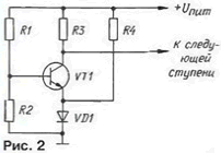
Offer threshold node of the voltage regulator to build a little differently (Fig. 2). In this embodiment, a threshold element continues to serve as the transistor VT1, and stabistor VD1 is operating normally provided by resistor R4. It is easy to see that the current through stabistor not only depends on the base current of the transistor.

When the voltage u pit. a smaller set, the transistor is closed by the fall voltage stabistor When the voltage u pit increases, reaches the set value, the voltage on the base will be sufficient for opening of the transistor.
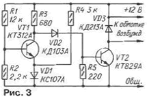
With the described variant threshold module was fabricated and tested a sample on-Board voltage regulator for the car. Circuit device it is shown in Fig. 3. The stabilizer was installed on the generator instead 29.3701 dismantled R112.

While vehicle voltage is small, the transistor VT1 closed and VT2 - opened. Through the excitation winding of the generator current flows. therefore, the voltage u pit, increases. Once it exceeds the threshold level, the transistor VT1 opens and VT2 closed - voltage begins to decrease until closing of the transistor VT1.
Required for stable operation of electric stabilizer "hysteresis" the switching transistors in the stabilizer is obtained automatically due to non-zero resistance of the connecting conductors. For this reason, the input a voltage divider R1R2 should not be connected directly to the output battery Rhea, as is so often recommended to improve stability voltage.
Diode VD2 is designed for reliable closing of the transistor VT2, when the transistor VT1 is open. Diode VD3 extinguishes the surge of self-inductance of the excitation winding generator when closing the transistor VТ2.
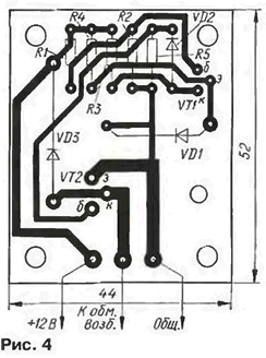
The stabilizer is assembled on a printed circuit Board of foiled fiberglass 1.5 mm thick. a Drawing card is presented in Fig. 4. The transistor can KTA replace CTA.

The required voltage of the switching regulator is established by establishing selection of resistor R2. The process of establishing repeatedly described in the journal (for example, in [3]), therefore here omitted. With a properly adjusted the stabilizer at a temperature of +40°C voltage supported by the generator, equal to 13.6 V. and at -20°C To 14.5 V.
Tests have shown that the instability of the voltage does not exceed ±1.5 %. I stabilizer with traditional threshold node, the figure was ±5 %.
The best results in the operation of the stabilizer can be achieved if to ensure thermal contact of the transistor VT1 and stabistor VD1с one of the side the walls of the battery.
Literature
Author: V. Bowker, Korolev, Moscow region.


