


")

Have long been aware of the fact that the charge electrochemical power sources asymmetric shock, when the ratio SAR : RESR = 10:1, in particular acid batteries, leads to the elimination of sulphation of the plates in the battery, i.e. to restore their capacity, which, in turn, prolongs the battery life.
It is not always possible to be near a charger all the time and to control the charging process, so often or systematically nodosaria batteries or recharge them, which, of course, does not extend the term of their service.
From chemistry it is known that the potential difference between the negative and positive plates in the battery is 2.1 In that with 6 banks gives 2.1 x 6 = 12.6 V.
At a charging current equal to 0.1 of the battery capacity, at the end of charge voltage is increased to 2.4 In one Bank or 2.4 x 6 = 14,4 V. Increasing the charging current increases the voltage at the battery and increased heating and boiling of the electrolyte. The same charge current is below 0.1 by capacity does not allow to bring the voltage up to 14.4 V, however, long-term (up to three weeks) charge a small current helps dissolve the lead sulfate crystals. Especially dangerous dendrites lead sulfate, "sprouted" in the separators. They cause a rapid discharge of the battery (from the evening charge the battery, and in the morning could not start the engine). Wash the dendrites of separators only by their dissolution in nitric acid, which is practically impossible.
Through long-term observations and experiments was established electrical circuit that, according to the author, allows you to trust the automation. Trial operation for 10 years showed efficient operation. The principle of operation is as follows:
1. The charge is produced on the positive half-wave of the secondary voltage.
2. On the negative half-wave there is a partial discharge of the battery due to current flow through the load resistor.
3. Automatic switching on when the voltage drop due to the discharge to 12.5 V and automatic disconnection from the mains 220 V when the voltage on the battery 14.4 V.
Disabling the non - contact, through the triac and control circuit voltage on the battery.
An important advantage of the method lies in the fact that until a battery is connected (automatic mode), the unit cannot be switched on, which prevents a short circuit when the circuit wires, supply charging current to the battery.
With a fully discharged battery, the inclusion of the unit is possible by means of the switch "AUTOMATIC-all the time."
Another very important advantage is the absence of a strong "boil", and, in conjunction with automatic switch off and turning on the included allows you to leave the device unattended for a long time. The author experimented with a two-week regime of permanent inclusion in the "AUTOMATIC"mode.
For the purposes of fire safety it is necessary that the charger was in a metal case, the cross section of inlet conductors to the battery - not less than 2.5 mm2. Mandatory also a reliable contact on the battery terminals.
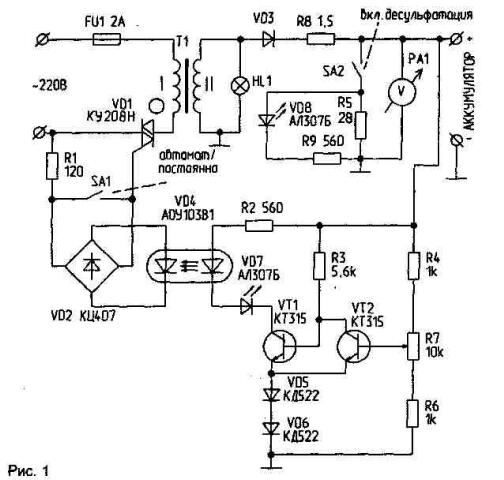
The mains voltage of 220 V is applied across the fuse FU1 and triac VD1 to the primary winding of the power transformer. Since the secondary winding of an alternating voltage U2=21 is rectified In the diode VD3 and through a ballast resistor R8 resistance 1.5 Ohms is supplied to terminal "+" of the battery connected to the voltmeter RA1 15, the switch SA2 on.DESULFATE" and the scheme of control and management, representing a Schmitt trigger with hysterization about 1.8 V, determined by the voltage drop across the diodes VD5, VD6 and the junction between the base and the emitter of the transistor VT2. Transistor VT1 when the battery voltage 12.6 V turns on, and through the optocoupler VD4 includes a triac VD1, which leads to the inclusion of the transformer T1 and the supply voltage for the battery being charged.
Connect the switch SA2 resistor R5 provides the asymmetric shape of the charging current. LEDs VD7 VD8 and indicate the unit is switched on in the modes DESULFATE" and "on" respectively. Resistor R7 sets the cut-off unit when the voltage on the voltmeter 15 B (=0.5 V falls on the lead wires). The bridge VD2 turn on the triac at both half waves of the mains voltage and normal operation of the transformer. The switch SA1 is used to switch to "CONSTANTLY".
Details. Power transformer - P=160 W, Uii=21, wire - sew-2 to 2.0. R8 - wire (nichrome) with a diameter of 0.6 mm. R5 - PMR 10…15 watts. Diode VD3 - any of D…D with any letter index on the radiator area S=200 cm2. The other type resistors - MLT, SP; triac - KUN without a radiator. S1 - any example MT. S2 - TB1-1. HL1-any lamp for 12 V RA1 - probe head 15 V.
Author: A. Sorokin, Ukraine, Kramatorsk; Publication: N. Bolshakov, rf.atnn.ru