The main disadvantage of the ignition system heater with candle - bulb is very large current consumption, especially during the startup of the heater.
In the magazine have been described more economical electronic devices (A. Kuzminski, V. Lomanovich. Heater start. - "Radio", 1975, N 6, p. 29), however, they require a voltage Converter 12/220 V. in addition, they do not provide safe operation of the heater. Indeed, if for any reason at its igniting the spark disappears high voltage, danger of explosion in the combustion chamber of the heater, since the fuel there continues to flow for some time.
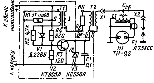
An electronic device which is schematically depicted in Fig. 1, provides increased reliability of operation of the heater and high efficiency (power consumption is less than 2.5 A). In the gap of spark plugs wifi device is formed not by a single level, and the "sheaves of sparks. It is equipped with an indicator light of a neon tube H1, which is lit only when the bit interval of the ignition lance penetrated by a series of sparks. The transistor V2 is protected from over-voltage diode VI and Zener diode V3.

Fig.1
The oscillator pulses are assembled high voltage transistor V2, the feedback transformer T1 and the ignition coil T2. The generation frequency of about 150 Hz. Capacitor C1 and resistor R4 determine the mode of operation of the generator. The resistor R1 is necessary for the coordination of the ignition system with a device for the automatic heater.
The indicator "sheaf" sparks is a impact excitation circuit consisting of inductor L1 and the capacitance of the coaxial cable. Through constructive capacity CERs circuit is associated with a high voltage circuit. Contour-parallel enabled neon lamp H1. It is mounted on the end of the segment of coaxial cable. The lamp is installed in the vehicle in a location convenient for observation.
Transformer T1 is made on the yoke Sh. Winding I is composed of 18 turns of wire sew-2 0,86, wound in two wires, and II - 72 turns of wire PELSHO of 0.3. Ignition coil T2 of the ignition system of the car "Zaporozhets". The Zener diode V3 is fixed in the centre dural plate radiator dimensions HH mm. Zener diode can be replaced by a chain of Zener diodes with a total voltage stabilization 150 V. the Transistor V2 is also installed on the same heatsink dimensions HH mm.

Fig.2
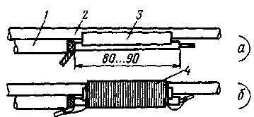
For the manufacture of the indicator necessary piece of coaxial cable RK-75-4-12A no longer than 75 cm, cut a length of 70-80 mm ferrite rod F with a diameter of 8 mm from the magnetic antenna and wire PELSHO of 0.3. Cable 1 with one of the cut ends as shown in Fig. 2,and. This finish is applied in a convenient location to the high voltage wire 2 connecting the ignition coil T2 with ignition spark F1, placed next to the ferrite rod 3 and the resulting wrapped package with a single layer of PVC insulation tape. On top of the tape on the entire length of the ferrite rod tightly round in a single layer wound coil 4, the ends of which are soldered to a coaxial cable (Fig. 2,b). Outside the winding isolate five or six layers of electrical tape. At the second end of the cable raspalaut neon light HI. Metal braid of the cable is securely connected to the vehicle body.
Spark plug A7,HSS for installation in the heater should be improved, as shown in Fig. 3. On the cylindrical part with a diameter of 21 mm the plug body thread. Thread is still incomplete, but sufficient to secure it in the hole where screwed to the threaded sleeve, attaching the glow plug. The side electrode of the spark gap of the spark folded, as shown in the figure. In the groove spark between the newly threaded and socket "turnkey" before installing the candles on the heater should be wound two or three turns of asbestos cord.

Fig.3
The negative terminal of the ignition system is connected to the vehicle body, and a positive wire, previously attached to the glow plug.
The inclusion and operation of the heater remains the same, the only difference is that the indicator system is provided by the lamp H1 and eliminates the need for the time delay for heating coils of the heater.
Author: D. Nazarov Lviv; Publication: N. Bolshakov, rf.atnn.ru


