The principle of "forget-me-nots" described in the article "Project "forget-me-not" ("Radio", 1997, No. 10 pp. 6 - 9), can be used to protect the car from capture the attackers. The article describes the nodes that need to change or to add to the already published design to "forget-me-not" could work in car.
A security system that prevents theft of the vehicle from the Parking lot, garage, etc p., of little help when armed assault on the driver during the journey. But robbery is meaningless if the robbers will not be able to use his acquisition. The idea behind the device is simple and is known to block normal operation of the electric equipment of the car after capture, i.e. in the presence of owner, everything works, and when it remains on the sidelines (with miniature a radio transmitter) - the engine stops.
Almost all of the elements of the device have already been described (see the article "Project "forget-me-not"). Here - and high-efficiency miniature radio transmitter that generates a pulse the radio signal and the radio receiving the signal only in a very small distance. It only remains to replace the electronic components of the radio receiver, forming in "the Forget-me-not" disturbing the acoustic signal, on the other and including the switching-off of the electromagnetic relay. This can be done, for example, as it is shown in Fig. 1.
If the radio receives signals from the transmitter, at its output (on header not shown in Fig. 1 transistor VT1) occur periodically repeating short pulses. These pulses regularly return DD2 counter to zero the condition, which corresponds to a low level on all outputs. The outputs elements DD1.3 and DD1.4 there is a high level, the transistor VT2 open, relay K1 is activated and leads to the electrical components in the working state.
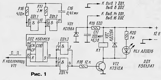
But if the distance between the receiver and the transmitter exceeds the limit (a few meters), the pulses at the input R of the counter DD2 will disappear. The multivibrator to the elements DD1.1, DD1.2 (excited at a frequency of about 0.5 Hz) start to change the counter state DD2, and 16 with a high level appears at its output 9 (pin 11). Respectively at the outputs of inverters DD1.3 and DD1.4 set the low level, the relay K1 is turned off and the car's electrical system will be blocked. As a further account in DD2 impossible (at its input CP - a high level), this status remains until the appearance of the first pulse.
With the Zener diode voltage VD1 +5.5 to 6 In to power the radio. Led HL1 preferably displayed on the dashboard of the car - he will inform the owner about the status of the security system.
How the relay contacts will be used to lock the electrical car, depends on the ability and imagination of the owner.
In table. 1 shows the parameters of some relays. Good, of course, relays and other types. It is only important that the selected relay had the 12 volt winding resistance not less than 25 Ohms.

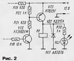
In the case of powerful relay or contactor capable switching currents in the tens of amps, electronic key is better to do as it is shown in Fig. 2.
The establishment of a receiver with relay output no features has not. Radio and actuating relay set secretly, in a remote place. The placement of the receiver may be tricky business. And although it's equipped with a magnetic antenna having a reduced sensitivity to electrical interference from the ignition system, might need to put in order all the vehicle's electrical system: to improve the wiring (some to put in the screen), install the filters.
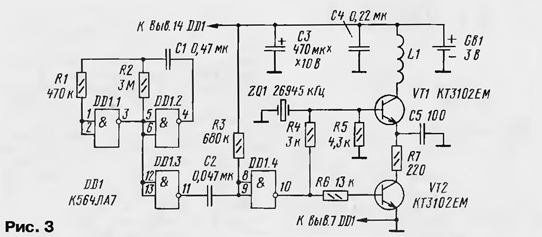
Although the transmitter "forget-me-nots" can work in this system without any alterations, it is better to do other more suitable. Its schematic diagram (Fig. 3) from the prototype is almost the same: withdrawn only RC circuit, lowering the voltage power the chip and changed the values of some resistors and capacitors. But this transmitter is powered from another source - compact lithium element (011,6x5,4 mm, voltage - 3, capacity - 130 mA·h).
The main changes are encompassed in design and are intended to make the transmitter is more flat. Hence not the usual configuration of the PCB (Fig. 4), round neckline which is placed a power source.
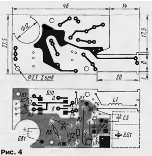
In the neck 14x18,5 mm establish a standard quartz resonator and the oxide capacitor dimensions 6x12 mm On figure ledge pay-wound coil L1 - 35...40 turns of wire PAVLO-0.25 mm. This is the "magnetic antenna" of the transmitter.
In three places charge "pierce" jumpers a, b and c (when installing the chip you need to ensure that the jumpers a and b did not touch her "bottom"). Connection conclusions resistors, capacitors, etc. General wire are shown as black the squares. When soldering the terminal of the resistor R1 - R3, capacitors C1 and C2 to pins (items) recommended miniature a soldering iron with a tip diameter of not more than 2.5 mm, with slim angled slot.
All resistors - MLT-0,125, ceramic capacitors are the most compact, better - with side pins. All elements are mounted so that their elevation above the Board did not exceed 4 mm. Transistors CTEM (plastic housing) stack the notched segment directly on the foil. By following these recommendations, the height fully assembled Board will not exceed 6...6.5 mm and, respectively, enclosed in a strong enough case the transmitter will be pretty flat - not thicker than 8 mm.
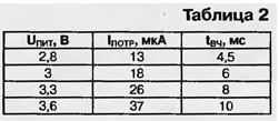
Repetition frequency radio transmitter depends on the frequency of excitation multivibrator elements DD1.1, DD1.2 (see Fig. 3). When indicated in the diagram the values of this frequency is about 0.5 Hz. The duration of the emitted radar pulse tвч leaves less than t, is the duration of a single pulse at the output of DD1.4, allowing the excitation of the transmitter. t = 0.7R3C2 = 22 MS. In table. 2 shows according consumed by the transmitter current (Potr) and tвч from u pit - voltage power source
About the power switch. On the one hand, he is not very necessary since consumed by the transmitter current will not change the power source of more than half a year (element soldered and forget about it all the time). But with this switch same source and can last 10 years, since the discharge of the lithium element very small (within 10 years of its stored energy is reduced only by 10... 15%). But even if the switch is of very good quality (sealed, gold plated contacts, etc.), in this construction it will be probably the most unreliable element. Original power switch may be a loop of thin wire breaking during forcible seizure of microtransmitter from the driver. Successful repairs near svezheokrashennym a stalled car seems unlikely.
The establishment of the transmitter is reduced to the selection of a quartz resonator. The resonator may not be suitable and in frequency (as experience shows, the difference between the frequency affixed to the resonator body, and that at which it actually excited, can reach up to a few kilohertz). Selection of quartz the resonator is much easier if you will be soldered to the Board is not himself, and short "through" the nest from any suitable connector having inner diameter 1 mm, for example, RM.
To ensure the normal operation of the transmitter can not only respond to it the radio system itself, but with the help of nearby CBS the radio station. It needs to be put into the channel 39 of the grid In the European frequency scale (this is the frequency 26945 kHz), and a transmitter to transfer in continuous mode radiation connecting the inputs of the element DD1.4 with the common wire.
If the same device, it should be remembered that the operation of the the device should not lead to an emergency situation.
Author: Y. Vinogradov, Moscow


