")

This circuit features an intermittent siren output and automatic reset. It can be operated manually using a key-switch or a hidden switch; but it can also be wired to set itself automatically when you turn-off the ignition. By adding external relays you can immobilize the bike - flash the lights etc.
Schematic Diagram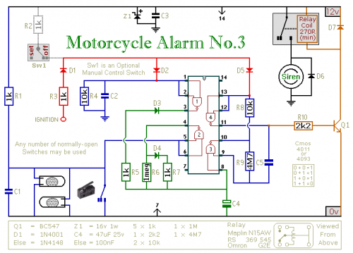 Notes
Notes
Any number of normally-open switches may be used. Fit "tilt" switches that close when the steering is moved or when the bike is lifted off its side-stand or pushed forward off its centre-stand. Use micro-switches to protect removable panels and the lids of panniers etc.
Once activated - the rate at which the siren switches on and off is controlled by R9 & C5. For example - increasing the value of C5 will slow it down - while reducing the value of R9 will make it faster.
While at least one switch remains closed the siren will sound. About thirty seconds after all of the switches have been opened, the alarm will reset. How long it takes to switch off depends on the characteristics of the actual components used. You can adjust the time to suit your requirements by changing the value of R6 and/or C4.
The circuit is designed to use an electronic Siren drawing 300 to 400mA. It's not usually a good idea to use the bike's own Horn because it can be easily located and disconnected. However, if you choose to use the Horn, remember that the alarm relay is too small to carry the necessary current. Connect the coil of a suitably rated relay to the "Siren" output. This can then be used to sound the Horn - flash the lights etc.
The circuit board and switches must be protected from the elements. Dampness or condensation will cause malfunction. Connect the 1-amp in-line fuse AS CLOSE AS POSSIBLE to your power source. This is VERY IMPORTANT. The fuse is there to protect the wiring - not the alarm. Exactly how the system is fitted will depend on the make of your particular machine - so I'm unable to provide any further help or advice in this regard.
The quiescent (standby) current of the circuit is virtually zero - so there is no drain on the battery. If you want to operate the alarm manually use a key-switch or a hidden switch connected to the "off/set" terminals. For automatic operation connect a wire from the ignition circuit to the "ignit" terminal. Then every time you turn-off the ignition - the alarm will set itself. Remember that this wire from the ignition switch is not protected by your 1-amp inline fuse. So unless its run is very short - fit the wire with its own 1-amp fuse as close as possible to its source.
When you set the alarm - if one of the switches is closed - the siren will sound. This could cause annoyance late at night. A small modification will allow you to Monitor The State Of The Switches using LEDs. When the LEDs are all off - the switches are all open - and it's safe to turn the alarm on.
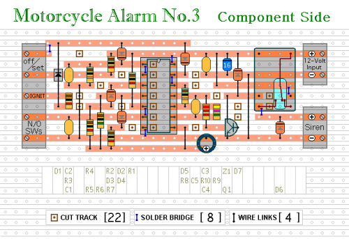
Veroboard Layout