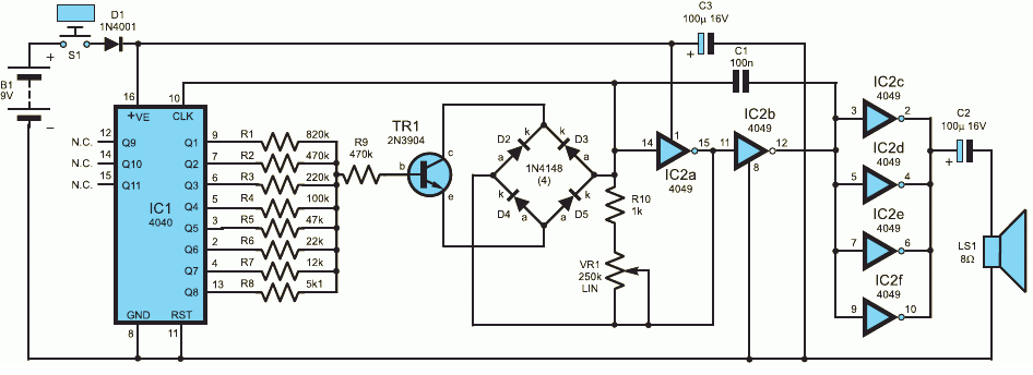
We offer you a scheme that is able to amuse children. It can to generate the sounds of police car siren, warble of birds, the sounds of space ships, etc. in addition, the scheme can be used in calls or door be used in signaling. This scheme is easy to make and it contains inexpensive components.
The scheme consists of four parts: a binary counter, a digital-to-analog Converter (DAC), generator, voltage controlled (VCO) and output audio amplifier. The speed with which he considers the counter, depends on the frequency of gun on it the output and frequency of the modes in turn is determined by the counter. This loop return connection and generates an output signal.
According to the scheme shown in the figure, the initial frequency of the oscillator, collected on elements IC2a and IC2b is set by the potentiometer VR1 and the capacitor C1. In the beginning, the generator operates at a relatively low frequency, the frequency gradually increases the voltage at the output of the DAC.

(click to enlarge)
The DAC is a group of resistors R1-R8 connected to the output of the counter IC1, providing base current of the transistor TR1. When all the outputs of IC1 is installed low level, then through the base of the transistor TR1 will be a small current to flow, therefore, control voltage will be small. As the outputs the counter will appear logical units, will increase the base current transistor TR1, and therefore will increase the output frequency of the modes.
The GUN assembles the elements of the IC2a, IC2b, TR1, diodes D2...D5, the capacitor C1, the resistors R10 and VR1. The diode bridge operates essentially as a resistor, controlled voltage.
The buffer amplifier is built on four elements of IC2 connected in parallel, the amplifier output is connected to the loudspeaker LS1 through a capacitor C2. Level the output signal is sufficient for experimental purposes, for more the volume of the output amplifier can be replaced by a conventional VLF.
The connections in the diagram are produced in the usual way, wiring is not critical, but make sure the correct connection polarity of the power source to chips. Pressing the S1 button, you will hear a sound that will depend on the potentiometer VR1. That would change the effect, press the S1 button.
Author: Craig Kendrick of Sellen, Carbondale, PA, USA


