


")

Sometimes you want to enable and disable the device at the same time during the day. For example, to disable the bell in the apartment at night, turn on the kettle in the morning, etc. I use this timer for automatically mute your phone in the evening from 22 to 6 am (8 hours), that gets rid of accidental calls.
The timer is provided with a resolution of one minute setting the desired time interval and repeating the process after 24 hours. Timer consists of a generator of the minute pulse on the chip D1, frequency dividers with a variable division ratio of D2 and D3 (16 inputs for setting the coefficient division) and the shaper short pulses on the elements of the chip D4 (Fig. 1.33).
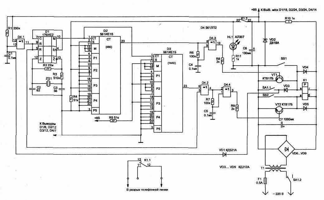
Fig. 1.33 (click to enlarge)
Switching circuits performs a polarized relay K1. It does not require constant power to the windings to maintain the position of the contacts, and for their relatively short switching pulse at the appropriate winding.
The circuit is based on readily available CMOS chips and features low quiescent current, which allows, if desired, to nourish her from the battery 9 V. In this case, the relay K1 is better to use with low-voltage work voltage, for example RPS RS4.520.755-08 (or RS4.520.755 - 18), and then the Zener diode VD2, HL1 led and resistor R10 don't need to install, and the capacitor C6 must increase of 1000 µf.
The circuit operates as follows. Timer switch is the SA1 toggle-switch in time from which you want to provide time interval. At the initial time when power is applied to the circuit until the charge of the capacitor C1, the output D4/11 is formed impulse, initial counter reset D1, and this same pulse through the elements of D4.2 , D4.4 will switch relay K1 (relay contacts 22 and 23 will be closed), and the inputs of the initial installation of the meter D2 appears logical "1" in accordance with the required ratio division (N).
The diagram shows the position of jumpers on the findings D2 for every 8 hours: N=8*60=480.
The division ratio for another time interval it is easy to determine using the correlation:
N=M(1000P1+100P2+10P3+P4)+P5 where
P1…P4 are adjustable coefficients, called multipliers thousands, hundreds, tens and units;
R5 - balance;
M is a coefficient called the modulus (the diagram shows the jumper settings for the values M=2).
The values of the decimal system numbers P1…P4 are set at the respective inputs of binary counters. So, for the division factor 1440: N=2(700+20)=1440 (P1=0, P2=7, P3=2, P4=0, P5=0); for the division factor 480: N=2(200+40)=480 (P1=0, P2=2, P3=4, P4=0, P5=0).
Once at pin D2/23 appears logical "1", element D4.1 generates a pulse to switch the relay K1 (pins 22 and 23 will open, and 12 and 13 will be closed). In this state, the scheme will be until at pin D3/23 appears momentum (log. "1").
Counter D3 has a division ratio of 1440, which corresponds to 24 hours. Through this interval, since the switching timer, the output of the counter will periodically receive a signal for automatic switching circuits. Depending on which group of contacts of relay K1 is used, the device can be enabled or disabled during the day for the necessary time interval.
When managing a powerful load, such as heaters, you must use an additional intermediate relay with the appropriate valid current through the contacts for the load capacity of 2000 watts current 10 A). Intermediate relay can be switched by contacts of relay K1, which are designed for maximum current not more than 0.5 A.
If in the process of the timer is required for a time to turn on or off a connected device, without changing the cycle timer, you can use the appropriate buttons: SB1 - enable and SB2 - off.
When you disconnect the timer from the network, the second group of contacts toggle switch SA1.1 connects the winding of the SH relay K1 to the capacitor. Discharge via C7 the relay coil will allow him to work, and it will return its contacts to the starting position, no matter what stage of the cycle, we turned off the timer. This group contacts through the diode VD1 will accelerate the discharge of the capacitor C1 that will ensure the readiness of schemes to work in any time when you switch on.
The circuit has resistors C2-23, capacitors C1…C5 type K10-17, C6 and C7 type K50-24 63 V.
Quartz ZQ1 will suit any type with an operating frequency 32768 Hz (they are widely used in hours). The circuit has polarized relay type RPS RS4.520.735-01, but will fit many other types, for example RPS RS4.520.224. Mains transformer T1 must ensure that the voltage in the secondary the winding is sufficient for the applied actuation relays.
With proper installation, configuration scheme does not require. Verify the operation of the timer is convenient to make when applying to the input of counters (D2, D3) a second pulse from pin 4 of the chip D1. This should take into account, initial memorization of the division ratio is performed through three steps the input pulses.
Diagram of the timer does not change modes at short-term the disappearance of the mains voltage. But in order for the timer is narwhales during prolonged absence of mains voltage, you must apply the item backup power (9V), which is enough to feed only the chip.
Publication: www.cxem.net