


")

Turns-off your amplifier when idle for 15 minutes, Fed by amplifier tape-output
This circuit turns-off an amplifier or any other device when a low level audio signal fed to its input is absent for 15 minutes at least. Pushing P1 the device is switched-on feeding any appliance connected to SK1. Input audio signal is boosted and squared by IC2A & IC2B and monitored by LED D4. When D4 illuminates, albeit for a very short peak, IC3 is reset and restarts its counting.
Pin 2 of IC3 remains in the low state, the two transistors are on and the relay operates. When, after a 15 minutes delay, no signal appeared at the input, IC3 ends its counting and pin 2 goes high. Q1 & Q2 stop conducting and the relay switches-off. The device is thus completely off as also are the appliances connected to SK1. C5 & R9 reset IC3 at power-on. P2 allows switch-off at any moment.
Circuit diagram:
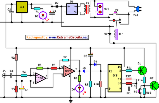
Amplifier Timer Circuit Diagram
Parts:
R1,R8___________1K 1/4W Resistors
R2,R3___________4K7 1/4W Resistors
R4_____________22K 1/4W Resistor
R5______________4M7 1/4W Resistor
R6,R9__________10K 1/4W Resistors
R7______________1M5 1/4W Resistor
R10___________100K 1/4W Resistor
R11____________15K 1/4W Resistor
R12____________10M 1/4W Resistor
R13_____________1M 1/4W Resistor
R14_____________8K2 1/4W Resistor
R15_____________1K8 1/4W Resistor
C1____________470µF 25V Electrolytic Capacitor
C2,C3,C6______100nF 63V Polyester Capacitors
C4,C5__________10µF 25V Electrolytic Capacitors
D1_____Diode bridge 100V 1A
D2,D7________1N4002 100V 1A Diodes
D3__________Red LED 5mm.
D4_______Yellow LED 5mm.
D5,D6________1N4148 75V 150mA Diodes
IC1___________78L12 12V 100mA Voltage regulator IC
IC2___________LM358 Low Power Dual Op-amp
IC3____________4060 14 stage ripple counter and oscillator IC
Q1____________BC557 45V 100mA PNP Transistor
Q2____________BC337 45V 800mA NPN Transistor
J1______________RCA audio input socket
P1_____________SPST Mains suited Pushbutton
P2_____________SPST Pushbutton
T1_____________220V Primary, 12V Secondary 3VA Mains transformer
RL1___________10.5V 270 Ohm Relay with SPST 5A 220V switch
PL1____________Male Mains plug
SK1__________Female Mains socket
Notes:
- Simply connect left or right channel tape output of your amplifier to J1.
- You can employ two RCA input sockets wired in parallel to allow pick-up audio signals from both stereo channels.
- The delay time can be varied changing R13 and/or C6 values.
- Needing to operate a device not supplied by power mains, use a double pole relay switch, connecting the second pole switch in series to the device supply.