


")

This circuit was developed since a number of visitors of this website requested a timer capable of emitting a beep after one, two, three minutes and so on, for jogging purposes. As shown in the circuit diagram, SW1 is a 1 pole 9 ways Rotary Switch. Setting the switch in position 1, the Piezo sounder emits three short beeps every minute. In position 2 the same thing happens after a 2 minutes delay, and so on, reaching a maximum interval of 9 minutes in position 9.
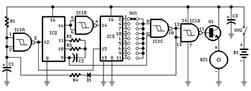
Circuit diagram:
Parts:
R1_____________47K 1/4W Resistor
R2_____________10M 1/4W Resistor
R3______________1M 1/4W Resistor
R4_____________12K 1/4W Resistor (see notes)
C1,C3__________10µF 25V Electrolytic Capacitors
C2____________100nF 63V Polyester Capacitor
D1___________1N4148 75V 150mA Diode
IC1____________4093 Quad 2 input Schmitt NAND Gate IC
IC2____________4060 14 stage ripple counter and oscillator IC
IC3____________4017 Decade counter with 10 decoded outputs IC
Q1____________BC337 45V 800mA NPN Transistor
SW1___________1 pole 9 ways Rotary Switch (see notes)
SW2___________SPST Slider Switch
BZ1___________Piezo sounder (incorporating 3KHz oscillator)
B1____________3V Battery (two 1.5V AA or AAA cells in series etc.)
Notes: