


")

In most cases, the measurement results of the analog data is best to read with the digital display. To this end, if necessary, apply various transducers (e.g. temperature-voltage, phase-voltage), the output signal of which serves on the ADC and then to the digital indicator. Described the device is convenient to use when you need an inexpensive meter average degree precision, and the use of single-chip ADCS for any reason impossible.
Scheme of two-digit indicator is shown in the figure.
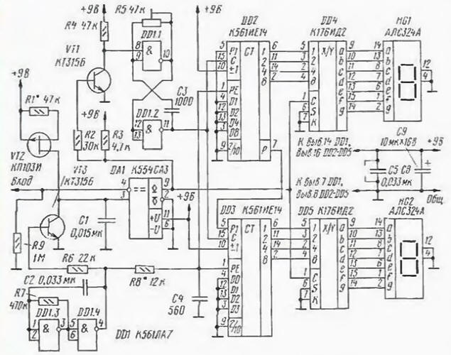
Measurement range voltage input 0…7 V. at higher voltage should be applied to the divider. The principle of operation of the ADC is based on measuring the charge time of the capacitor to voltage equal to the measured, and its subsequent conversion to digital form. The proportionality of the measured time and voltage is provided stabilization of the charging current.
The ADC is controlled by the generator of rectangular pulses on the elements DD1.3. DD1.4. When the output of the generator appears log. 0. transistor VT3 is closed and on inputs RE counters DD2 DD3 has a log. 0. allowing the counting of pulses with generator on DD1.1. DD1.2. The capacitor C1 is charged by the current generator on the transistor VT2. When increasing the voltage on the capacitor will be equal to input, the output 9 of the comparator DA1 appears high logic level. The VT1 transistor inverts it. therefore, the operation of the generator on the elements DD1.1 and DD1.2 is blocked. Simultaneously at the inputs WITH DD4. DD5 has a log. 1, permitting the recording of information from the meters DD2. DD3. Fixed number is displayed on the led indicators HG1. HG2.
As soon as the output of the generator on the elements DD1.3, DD1.4 will log. 1, open VT3 transistor and the capacitor C1 is discharged. The comparator DA1 changes its state and blocks the entry in the code converters DD4. DD5. Through a short period of time determined by circuit R8C4. log. 1 is fed to the inputs RYO counters DD2, DD3. recording them in the log. 0. After that, the measurement cycle repeats.
If the input voltage is zero, the output of the comparator DA1 high logic level is present, allowing the entry in DD4. DD5 and a blocking oscillator for DD1.1. DD1.2. Thus in counters DD2. DD3 is written zeros displayed by the indicators.
Structurally, the indicator is made of two boards: one is installed led indicators HG1. HG2: on the other - all the other elements. Mounting circuit boards can be performed by a printing method or a thin wire in isolation.
In the device used fixed resistors MLT - 0.125, capacitors C2 - C4 can be any ceramic. The trimmer R5 - SP5-2 or other multi-turn; the capacitors C1 and C3 - ceramic with low TKE, as C1 you can also set K73-17. Led indicators HG1, HG2, you can replace on ALSB (common anode) by connecting the inputs S code converters and General the electrodes of the LEDs to GND. Chip DD4. DD5 can be replaced CIZ. Transistors VT1.VT3-any of a series of KT315.
The establishment of the assembled device begin with installation of the charging current of the capacitor C1. For this include microammeter in the gap between the drain of the transistor VT2 and a connection point of the capacitor C1 to the collector of VT3 and the selection of resistor R1 set current of about 20 μa. Then fed to the input of the device voltage corresponding to the upper limit of the measuring range, and a resistor R5 establish indicators on the corresponding indication. Sometimes, when fuzzy the zeroing of counters (when the indicators are alternating zero and non-zero testimony), we need to find the resistor R8. After adjusting, changing the input voltage, check the operation of the device as a whole.
In the author's version of the described device is used as a voltmeter laboratory power supply.
Author: S. Kuleshov, Kurgan