When designing various automation devices and alarm happens need a sound indicator of the state of any node. Often, this the indicator is built on the basis of the generator AF loaded on a sound emitter. However, the monotonous sound of this indicator is often not enough to see, especially in terms of noise. Therefore, use methods of modulation signal, for example, interrupting or changing the amplitude or frequency.
Although such devices have also been repeatedly documented in the technical literature, they sometimes were complex and critical voltage of the power, the content is large the number of radioelements and winding details.
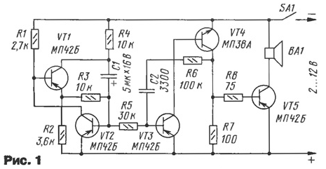
The proposed indicator is free from such drawbacks are not critical to the type the sound emitter and is able to cope with the large variation of the voltage power. The indicator (Fig. 1) consists of a control generator configured to transistors VT1, VT2, operated generator on transistors VT3, VT4 and the power amplifier transistor VT5.

Managing the generator produces pulses of triangular shape, with the following a frequency of about 2 Hz and the modulating frequency of the audio signal. His output the signal is outside the box - with the base of the transistor VT2 and is fed through a resistor R5 to the base of transistor VT3 controlled generator together with the transistor VT4 under the scheme of the multivibrator.
The output signal of the multivibrator is fed to a power amplifier through a resistor R8. Loaded amplifier dynamic head of BA1, which are dealt sounds.
Transistors VT3, VT4 must be a current transfer ratio of not less than 80, and VT5 must be able to withstand the power of a sound emitter. Settings the remaining transistors are not critical. If the supply voltage does not exceed 4, dynamic head can be power not less than 0.25 W with voice coil impedance of 8 Ohms. At higher voltages it is possible to install low-impedance telephone capsules, for example, TA - 4, TK - 67, DAMS - 1 AND DEM - 4M.
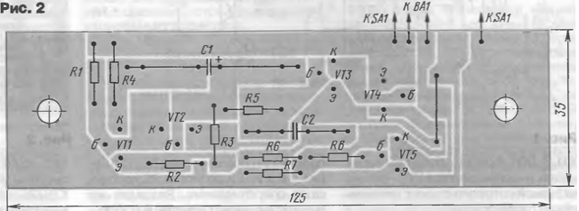
Constructive implementation of the indicator depends on the details. One option PCB of one-sided foil fiberglass depicted in Fig. 2. Isolating tracks cut by the cutter, made of cut saw blade (if it's not, fit sharp knife). If desired you can make a new drawing boards for the manufacture of its etching.

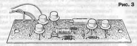
The fee is designed to install the resistors ULM or MLT, and also indicated in the diagram transistors. For the installation of condensers has multiple holes and the stock the square Board, which allows the use of capacitors of various types, particular, MBM, BM, KM, K50 - 6. The appearance of the assembled Board is shown in Fig. 3.

The Board is designed for mounting on the terminals of the battery SSNK - 10B (from mining lamp), for which her drilled two holes with a diameter of 6.5 mm at a distance of 107 mm When the mounting Board is provided by an electric the connection of the terminals of the battery with the printed conductors. To exclude corrosion of fees under the influence of evaporating the liquid from the battery, it should be coated with insulating varnish. The top charge, close the lid, for example, from the set of the specified lamp, but quite acceptable other options.
When establishing indicator desired tone alarm sound set selection of the capacitor C2, and the frequency of the modulation - C1.
Author: D. Volkov, Shakhty, the Rostov region.


