


")

Circuit diagram:
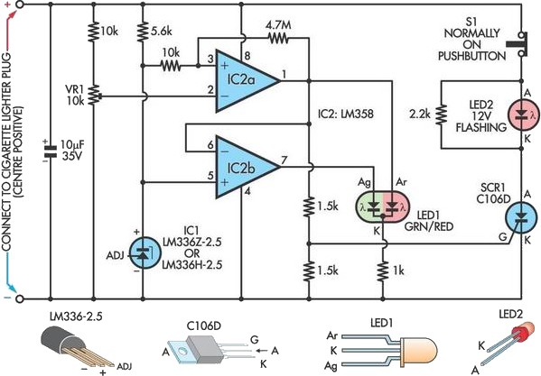 Car Battery Failure Detector Circuit Diagram
IC2a monitors the voltage from trimpot VR1 and normally its output at pin 1 will be low while the output of IC2b will be high and LED1 will be green. When pin 2 of IC2a falls below pin 3, its output at pin 1 will go high to drive the red section of LED1 to indicate a fault. At the same time, IC2b inverts the signal from pin 1 and its output at pin 7 goes low and turns off the green section of LED1 to indicate a fault. Since the battery voltage drop occurs momentarily while cranking, a more permanent indication of the fault is provided by flashing LED2. When IC2a’s output goes high momentarily, the SCR is latched and LED2 flashes and can only be deactivated by pressing pushbutton S1.
Author: Victor Erdstein - Copyright: Silicon Chip Electronics