


")

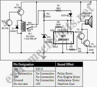 The output is available from pin 3. Two transistors BC147 (T3) and BEL187 (T4) are connected in Darlington configuration to amplify the sound from UM3561. Resistor R4 in series with a 3V zener is used to provide the 3V supply to UM3561 when the relay is in energised state. LED1, connected in series with 68-ohm resistor R1 across resistor R4, glows when the siren is on. To test the working of the circuit, bring a burning matchstick close to transistor T1 (BC109), which causes the resistance of its emitter-collector junction to go low due to a rise in temperature and it starts conducting. Simultaneously, transistor T2 also conducts because its base is connected to the collector of transistor T1. As a result, relay RL1 energizes and switches on the siren circuit to produce loud sound of a fire-brigade siren.
Note.
- We have added a table to enable readers to obtain all possible sound effects by returning pins 1 and 2 as suggested in the table.