The purpose and principle of operation
The principle of operation of the described device is based on the influence of eddy currents, emerging in a metal object, on the quality factor of the coil, creating magnetic field.
It can be used in many cases:
- for the detection of unwanted metal objects in the moving mass any raw material or finished products;
- for counting metal parts or the number of vehicles, the following via the control point, etc.
Schematic diagram
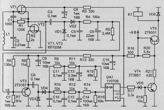
Schematic diagram of the device depicted in Fig. 2.26. It consists of four main parts:
- generator (VT1, VT2);
- the processing unit of the signal (VT3, DA1);
- electronic relay (VT4, VT5, K1);
- the sensor, which serves as a coil L1, forming the capacitors C1 and C2 the oscillating circuit of the generator.
The VT2 transistor serves as the source of stable current and dynamic the load of the transistor VT1. The amplitude of the generated oscillations is stabilized thanks to the source and drain of this transistor (through the integrated circuit and R4C6R5 the coil L1) DC component of the rectified diodes VD1, VD2 output voltage of the generator.
The node processing the signal comprises:
- the emitter-follower transistor VT3;
- the rectifier is performed by the voltage doubling circuit of the diodes VD3, VD4;
- the integrating circuit R9C11R11C13 and R10C12R12C14 with different time constants and the comparator at the shelter DA1.

Fig. 2.26. Schematic diagram of an apparatus for detecting a moving metal objects
In steady state the output voltage of the comparator is zero, the transistors VT4, VT5 closed, and the relay K1 is de-energized. At the time of power up, the potential of the gate of the transistor VT1 is zero, it the steepness of the maximum, and the generator snowspeeders. As the charging of the capacitor C6, the oscillation amplitude decreases smoothly and through a few seconds to stabilize at some level. Around this same time is set to zero, the voltage at the output of op-amp DA1.
At the approach of a metal object to the coil L1 loss in the circuit L1C1C2 increase, and the amplitude of the generated oscillations for some time (determined parameters of the circuit elements R4C6R5) falls. As a result, the voltage at the rectifier output (VD3, VD4), and with a small delay - and the inverting input of op-amp DA1 decreases. Since the potential of its the other input to this time change does not have time (due to the higher constant timing chain R10C12R12C14), the output voltage of the comparator abruptly decreases.
This opens the transistors VT4, VT5, and relay K1 is activated, feeding the command to stop the conveyor belt or including the alarm. Under these in the diagram component values of the integrating circuits, the device detects objects moving at speeds greater than 0.5 m/s.
Adjustment
The sensitivity can be adjusted, the adjusted resistor R1. Slow the voltage variations at the inputs of the integrating circuits (when the speed of movement metal objects is less than specified) do not cause the appearance of a difference potentials at the inputs of the shelter DA1, so the comparator does not work.
Not responding device and the stationary metal objects property location with a coil L1.
Used parts
Coil L1 is made in the form of a circular frame with a diameter of 320 mm and contains 250 turns of Litz magnet wire (Litz wire) 35 x PEL of 0.05. The inductance of the coil 42 mH, DC resistance of 32 Ohms. Frequency device-generated oscillations is about 23.5 kHz.
In your device, you can use the OS KUA, the series transistors KT315 (VT3), CT (VT4), CTA (VT5), diodes series D (VD1-VD5) and D (VD6), relay RES (passport RS4.524.202).
Author: L. Tenev.


