Functions and capabilities
This detector, despite the small number of parts and ease of manufacture, fairly high sensitivity. Large metal objects, such as a radiator, it is able to detect at a distance of 60 cm, small, for example, a coin with a diameter of 25 mm at a distance of 15 cm.
The principle of operation
The principle of operation of the device based on the change of frequency in the measuring the generator under the influence of nearby metals and the selection differential frequency (beats) between measurement and model generator.
Since this frequency is in the audible range, it can be heard in headphones.
Schematic diagram
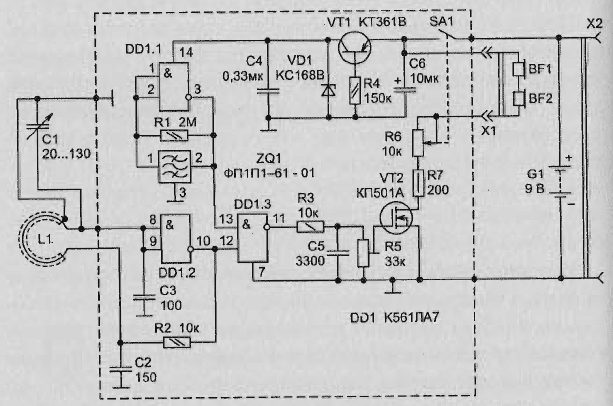
Schematic diagram of the detector is presented in Fig. 2.46. In this scheme the frequency of the reference oscillator, which is made on DD1.1, stabilized with of the piezoelectric element. As the piezoelectric element used piezophilic (ZQ1) an intermediate frequency (465 kHz) available in any household superheterodyne radio.
Such elements are widely distributed and much cheaper than quartz the resonators. The use of the piezoelectric element can improve the frequency stability reference generator compared to conventional LC or RC oscillators, and, therefore, to increase the range of detection of metal objects.

Fig. 2.46. A schematic diagram of a simple metal detector with piezotron
Measuring the generator is assembled on the logic element DD1.2 and includes a coil (L1) in the form of a frame, which is the sensor. When approaching the coil to the metal changes its inductance, which in turn changes the frequency of the oscillator. Initial frequency of the oscillator is determined by the elements and C1C2C3L1 adjusted by an adjustable capacitor C1, which is close to the frequency reference oscillator (slightly more or less than 465 kHz).
On the element DD1.3, the signals of the two oscillators are mixed. The output signal DD1.3 contains differential harmonic, and to separate it from the high-frequency pulses have a filter R3C5. The low-frequency signal is amplified field the VT2 transistor and fed to a sound emitter - headphones BF1 BF2.
Used in oscillators logic elements CMOS circuits, due to their a large input resistance, allows to obtain a high q resonant circuit search generator that increases it stability frequency. This gives you the opportunity to work with small beating and thus increase the sensitivity of the detector. The power oscillators stabilized with a precision Zener diode XV. Only parametric stabilizers at a voltage of about 6 To have close to zero drift voltage when the ambient temperature changes.
Diagram of the detector remains operational when the voltage to 5 In, but in this case the stabilization of the supply voltage will not. Quiescent detector current (and, hence, duration of work) much depends on the resistance connected at the output of headphones. On therefore, their resistance should be as large as possible (>100 Ohms), which phones the headphones are connected in series.
Resistor R7 limits the maximum current of the transistor VT2 during a short circuit in the headphones, and the resistor R6 allows you to adjust the sound volume. For convenience this resistor combined with the switch SA1.
Headphones connect via any standard socket.
Socket x2 is used to connect the AC charger to battery G1. This will allow to recharge the batteries without removing of the body.
Element base
The capacitor C1 can be rented from any miniature radio (for example, KP-180). C2 and C3 should be with minimum negative TKE (M47, M75), C4 and C5 from the K10 (K10-17), C6 - K53-1 on V. 16
Variable resistor R6 - CP3-BM (it provides for horizontal installation on circuit Board and has a built-in switch SA1), a setup resistor R5 type SDR-19a, the rest will fit any compact. Piezoresonator (piezophilic Z01) most likely will fit any from PPP-61 (-01, -02, etc.), and you can also try many other types of piezophiles the Chinese receivers with three conclusions.
The printed circuit Board
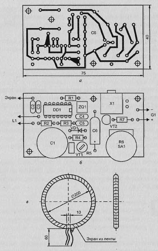
Parts of the device can be located on a single-sided PCB from fiberglass thickness of 1.5 mm and a size of 75 x 40 mm (Fig. 2.47, a-b).
The fee is preferably placed close to the sensor coil L1. The place where secured Board with components, screening not required.
Manufacturer of coil
Coil sensor detector L1 has the form of a toroidal frame, (Fig. 2.47 in). She is wound copper wire sew with a diameter of 1.2 mm on any suitable the mandrel diameter 20 cm, for example, carved from foam.
Coiling should be performed in bulk, 30 turns (inductance is about 480 µh). After winding coil frame must wrap any dielectric tape (varnished cloth or duct tape), and then a thin aluminum foil.
You can also use copper foil. At the terminals of the coil a section of about 10 mm close the foil is not necessary (between the ends of the screen is left a gap, as it it is shown in Fig. 2.47 in).

Fig. 2.47. A simple metal detector with piezophiles: a - circuit Board; - the location of elements on the Board; - the appearance of the search coil
The screen at the coil reduces the influence of parasitic capacitance, which increases the stability operating frequency of the search oscillator.
Use thick wire in the manufacture of L1 provides a higher q-factor of the coil and gives rigidity to the frame without the use of additional fastening elements.
Author: Shelestov I.


