The word "induction" in the title of detectors of this type completely reveals how they work, if you remember the meaning of the word "inductio" (lat.) - guidance. A device of this type is composed of one sensor coil any convenient form, excited by an alternating signal. The advent of near sensor metal object causes the appearance of the reflected (pereizluchennykh signal), which "induces in the coil an additional signal is electrical. Remains the additional signal only highlight.
The induction type metal detector has received the right to life, mainly -due to the lack of devices on a transfer-receiving" - complexity the design of the sensors. This complexity leads to a high cost and the complexity of the manufacturing process of the sensor or to its insufficient mechanical stiffness that causes the appearance of false signals while in motion and reduces the sensitivity of the device.
If you ask for delete at the instruments on the principle of "transmit-receive" this disadvantage by addressing the causes, then we can come to an unusual conclusion - emitting and the receiving coil of the metal detector should be merged one! In fact, it is highly undesirable movement and curves of the single coil relative to the other in this case, since only one coil and it is both emitting and reception. There is also extremely easy sensor. Pay for these advantages is the need for the provision of useful the reflected signal against a much larger excitation signal radiating/receive coil.
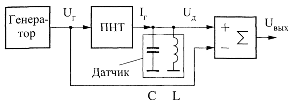
To distinguish the reflected signal can, if we subtract from the electrical signal, present in the sensor's coil, the signal of the same shape, frequency, phase, and the amplitude of that signal in the coil in the absence of metal near. 'How is that possible implement one of the methods shown in Fig. 3.

Fig. 3. Structural scheme of the input node of the induction metal detector
The generator produces an alternating voltage of sine wave with a constant amplitude and frequency. The Converter "voltage-current" (PNT) converts the voltage of the generator current IG in G, which is set in oscillation circuit sensor. An oscillating circuit consists
of capacitor C and coil L of the sensor. Its resonant frequency equal to the frequency generator. The conversion factor PNT is selected so that the voltage oscillating circuit ID is equal to the voltage of the generator IG (in the absence metal near the sensor). Thus, the adder is subtraction of two signals of the same amplitude, and the output signal is the result of the subtraction is equal zero. With the appearance of metal near the sensor, the reflected signal occurs (in other words, we change the parameters of the sensor coil), and this leads to a change voltage the arc voltage oscillating circuit. At the output a signal that is different from zero.
In Fig. 3 shows only the simplest version of one of the input circuits parts metal detectors of the type in question. Instead of PNT in the scheme in principle you can use dakotadome resistor. Can be used different bridge schemes to enable the sensor coil, the adders with different the transmission coefficients by inverting and positive inputs, partial the inclusion of the oscillation circuit, etc.
In the circuit in Fig. 3 as the sensor oscillating circuit is used. It made for simplicity, to obtain a zero phase shift between the signals and IG The arc voltage (it is tuned to the resonance). You can abandon the oscillating circuit with the need to fine tune it to resonance and to use as load PNT only the coil of the sensor. However, the transfer coefficient pot to do this case must be comprehensive in order to adjust the phase shift of 90°, occur due to the inductive nature of the load pot.
Author: A. I. Shchedrin


