


")

Recently on the shelves of radio markets, you can find all kinds designers or sets of components, which anyone purchasing effortlessly quickly gather simplest metal detector. The author had the pleasure to see several Junior designers that we can recommend and adults.
The basis for one of these sets was the scheme of the detector, for the first time published in the late 80-ies of the last century, and after that with different changes and additions than once published in various domestic and foreign editions.
Schematic diagram
Review metal detector is one of many variants of the device type BFO (Beat Frequency Oscillator), that is, device, based on the principle analysis of the beating of the two frequencies. When in this structure, the change of the frequency is done by ear.
As you know, to a certain extent, improve the sensitivity of the detector type BFO can, if we choose the value of the reference oscillator frequency in 5-10 times greater than the frequency of the measuring oscillator. In this case estimated beat frequency change that occurs between the oscillation the main reference oscillator frequency and the nearest harmonic frequency frequency measuring generator. As a result, the frequency change measuring generator under the influence of only 10 Hz leads to an increase the oscillation frequency difference of 50-100 Hz.
Thus, when selecting the frequency of the measuring oscillator within 100-200 kHz frequency of the reference oscillator must be 500-2 000 kHz. Need note that the frequency of the reference oscillator must be stable.
The basis of the scheme of this device (Fig. 3.12) are measuring and reference generators, buffer stages, a mixer and a scheme of acoustic indication.
Fig. 3.12. Schematic diagram of the detector with quartz stabilization
Reference oscillator is made on the elements of the IC1.1 and IC1.2 of chip IC1, operating frequency stabilized crystal resonator Q1 (1 MHz). Measuring or a tunable oscillator is made on the elements of IC2.1 and IC2.2 chips IC2. Operating frequency of this oscillator is determined by the parameters of the elements, forming its oscillating circuit, that is, the capacitances of the capacitors C2, C3 and the varicap D1 and the inductance of the coil L1. The change in capacitance the varicap D1 by using the variable resistor R2. Operating frequency measuring generator is in the range of 200-500 kHz. Coil L1 tunable oscillating circuit of the generator is search coil. When approaching a metal object coil inductance changes which in turn changes the operating frequency of the generator respectively and change the beat frequency.
Cascades performed on the elements of the IC1.3 and IC2.3, provide isolation between generators DC voltage, and also weaken the influence of the mixer in generators. From the outputs of buffer stages, the RF signals are fed to the mixer, performed on the element IC1.4. Further, the beat signal is supplied to the head phones BF1. When the capacitor C10 provides filtering of high frequency component of the signal.
The power to the circuit is supplied from the source B1 with a 9 V through the filter, formed by the capacitors C8 and C9.
Details and design
All the details of the proposed instrument (with the exception of the search coil L1, resistor R2, connectors X1 and x2, as well as switch S1) located on the printed PCB size 50x50 mm (Fig. 3.13), made of one-way foil Micarta or phenolic resin.
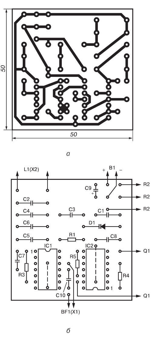
Fig. 3.13. Printed circuit Board (a) and the arrangement of elements (b) with the metal detector quartz stabilization
To detail used in this device without facing any special requirements. It is recommended to use any small-sized capacitors and resistors that can be placed on the circuit Board. In this case the fee is calculated on installation of fixed resistors type MLT-0,125 or other small-sized (e.g. MLT-0,25 or sun-0,125). Capacitors C2, C3, C5 and C7 can be type CT-1, capacitors C4, C7, C8 and C10 - type km-4 or K10-7V, and capacitor C9 - type K50-6.
Variable resistor R2 can be any small, however, as such a the regulator is not recommended to use resistors, mechanically connected with the power switch S1.
Quartz crystal Q1 is mounted on a separate Board from fiberglass, mounted parallel to the primary-side parts. Its frequency can be either in the range of 0.5-1.8 MHz. However, if you will be using the quartz resonance frequency greater than 1 MHz, in some sources it is recommended between the output of the buffer element IC2.3 (the output of IC2/10) and the corresponding input mixer on the element IC1.4 (the output of IC1/13) include a frequency divider, a second an exemplary frequency of 0.5-1 MHz. Such a divider can be performed on the chip series C or K.
The search coil L1 contains 50 turns of wire pelsho diameter of 0.27 mm and made in the form of a ring with a diameter of 180-220 mm. This reel is easier to make on a a rigid frame, but you can do without it. In this case, as temporary frame may be any suitable size round subject. The turns of the coil are wound in bulk, and then removed from the frame and with the purpose of increasing the mechanical strength of the impregnated epoxy glue. Then coil L1 is screened electrostatic screen, representing unconfined tape aluminum foil is wound on top of the harness turns. The gap between the beginning of and the end of winding of the tape (the gap between the ends of the screen) should be at least 15-20 mm. In the manufacture of the coil L1, it is necessary to ensure that not there was a short circuit ends of the shielding tape, as in this case closed loop is formed. To protect from damage the foil can wrap one or two layers of electrical tape.
A source of audio signals can serve as high impedance headphones type TONE-2, TA-4 or similar.
As the power source B1 can be used, for example, the battery "Krona" or two batteries type 3336L connected in series.
Printed circuit Board with the controls it contains and the power source are placed in any suitable metal enclosure. On the housing cover installed variable resistor R2, connector X1 for connection of headphones BF1, connector X2 for connecting the search coil L1 and a switch S1.
Establishing
This appliance should be set up in conditions when metal objects removed from the search coil L1 at a distance of not less than 1.5 m.
The process of setting up the metal detector is to configure the measuring the generator frequency 100-200 kHz, which occurs by adjusting the capacitance values of of the capacitor C2. This engine variable resistor R2 must be in the middle position. The frequency of the measuring oscillator is controlled by the frequency at the output of the element IC1.3 (the output of IC1/10). Control the correctness of the chosen the frequency of the measuring oscillator is listening the difference frequency in the head phones. This signal must be sufficiently loud at the greatest possible frequency ratio of the reference and measuring generators. When it is necessary to estimate the amplitude of the beat signal can to use the oscilloscope.
The order of work
In the practical use of this device should be a variable resistor C1 to maintain the desired signal frequency of the beats, which can change under the influence of various factors (for example when changing the magnetic properties of the soil, the ambient temperature or battery discharge).
If in the process of work in the area of the search coil L1 will be any metal object, the signal frequency will change. When approaching among metals, the frequency of the beat signal will increase when approaching others will decrease. To change the tone of the beat signal, having some experience, you can easily determine the kind of metal, magnetic or non-magnetic, made detected object.
With the help of this device small objects (e.g. coin medium size) can be detected up to a depth of 80-100 mm, and a manhole cover on the depth of 55-65 cm
Author: M. V. Adamenko