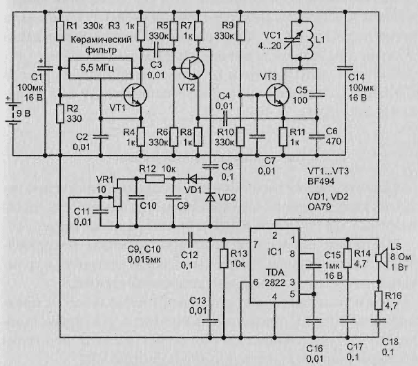
Schematic diagram
The scheme presented in Fig. 2.48 is a classic metal detector. Work the scheme is based on the principle of superheterodyne frequency conversion, which typically used in the superheterodyne receiver.

Fig. 2.48. Schematic diagram of the detector with integral unch
Uses two radio frequency generator, the frequency of which is 5.5 MHz.
The first RF generator is assembled on the transistor T1 type BF494, frequency generator stable quartz. Used ceramic filter frequency 5, 5 MHz, which is commonly used in the tract if the TV sound.
The second RF generator according to the scheme "Kapitza" assembled on the transistor T3. Frequency is set by the parameters of inductance L1 and a capacitor VC1.
The frequencies of the two RF generators are mixed in the mixer, assembled on the transistor T2. The difference frequency signal from the collector of transistor T2 is supplied the detector collected the diodes D1 and D2. Ripple voltage smoothing the low pass filter assembled on the elements R12,C6,C10. Through the regulator level signal is then supplied to the low-frequency amplifier.
The inductor L1 has 15 turns of wire PEL of 0.25 wound on the mandrel of diameter 10 cm and fixed with varnish.
Setting of the metal detector
After setting up the frequencies of both oscillators in the absence of metal objects the frequency must match exactly to the ULF to get zero runout frequency difference.
It is the selection of the nominal value of trimmer capacitor VC1. When the correct setting in the speaker there is no tone difference frequency.
When you appearance near the coil L1 of metal objects, the frequency of LC oscillator changes in the loudspeaker to listen to the tone difference frequency. It the volume is controlled by the variable resistor VR1.
Author: Akindinov A., UA3VVM; publication: www.electronic-lab.com


