


")

The basis of operation of the detector circuit and structure as considered in this section is based on the principle of analysis of changes in the beating of two oscillations generators, the frequency of one of which is stable, and changes the frequency of the second when the detection of a metal object.
When working on this unit, an attempt was made to create a metal detector, free from several disadvantages inherent in other similar designs.
Although the circuit of this device has been developed over 20 years ago, to its advantages include a relatively high sensitivity, stability in the work, and the ability to distinguish between ferrous and non-ferrous metals. Used circuit solutions has provided increased stability operating frequency generators that allowed us to estimate the beat frequency in the range from 1 to 10 Hz. As a consequence, increased the sensitivity of the device, and decreased consumed current.
Schematic diagram
As already indicated, the proposed design represents one of numerous options of detectors type BFO (Beat Frequency Oscillator), that is, a device, based on the principle analysis of the beats the two frequencies (Fig. 2.10).
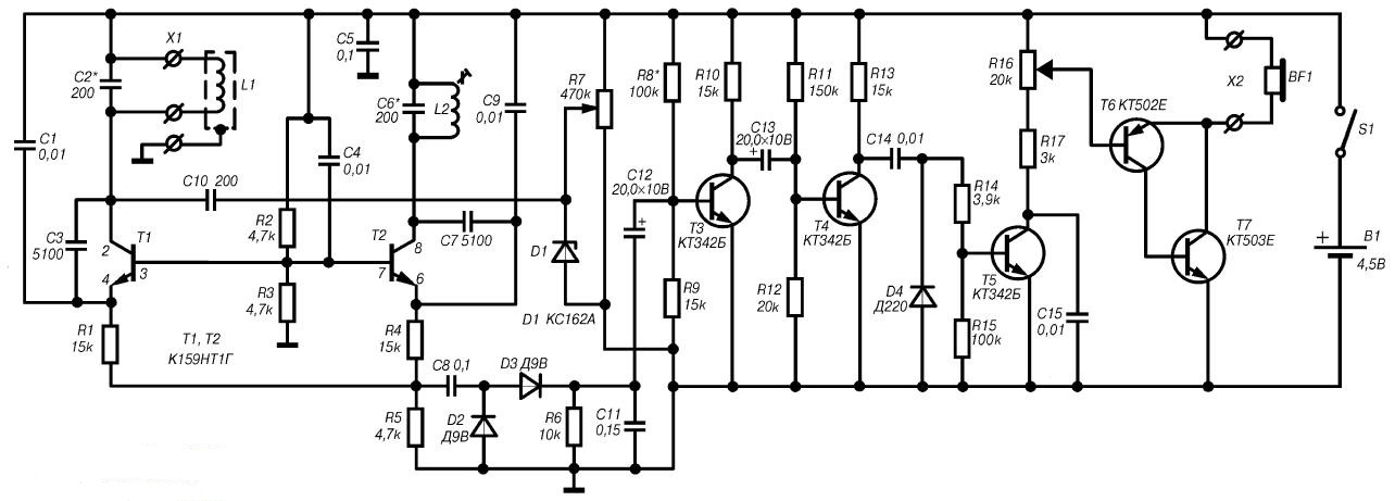
Fig. 2.10. Schematic diagram of the detector with high sensitivity (click for enlarge)
The instrument consists of a measuring and reference generators, detector HF oscillations, pre-amplifier, the first amplifier-limiter, the differentiating circuit, the second amplifier-limiter and the low-frequency amplifier.
As the measuring and the reference generator used two simple LC-oscillator, transistors T1 and T2. These transistors are the composition of the chip CNG, which is a pair of identical the parameters of the transistors placed in a single package. Use transistor Assembly can significantly improve temperature stability frequency generators.
Each generator is built on a capacitive treatacne, the transistors T1 and T2 is connected in the circuit with a common base.
The excitation of vibrations is ensured thanks to the introduction of positive feedback the connection between the collector and emitter of each transistor. Operating frequency of generators is determined by the parameters of frequency-selective networks connected between the collectors and the emitters of transistors T1 and T2. Thus customizability the elements of the first generator, which performs the function of measuring generator are the search coil L1 and capacitors C1, C2 and C3. Working the frequency of the second reference, the generator is determined by the parameters of the coil inductor L2 and capacitors C6, C7 and C9. Both generator tuned to a working frequency of 40 kHz. Using resistors R1-R4 is provided setting of operation modes of the transistors T1 and T2 DC.
During configuration of the device by changing the capacitance of the capacitor C6 is coarse adjustment of the reference oscillator to a selected harmonic of the beat frequency. When the capacitance of the capacitor C6 may vary from 100 to 330 pF. Fine tuning of the beat frequency is a variable resistor R7, through which changes the bias on the Zener diode D1, which in this scheme acts as a varicap.
When approaching the search coil L1 tunable resonant circuit generator a metal object, its inductance is changed, which causes changing the operating frequency of the generator. In this case, if near the coil L1 is the subject of black metal (ferromagnetic), its inductance increases, which decreases the frequency of the generator. Colored metal reduces the inductance of the coil L1 and the operating frequency of the generator increases.
The radio frequency signal generated by mixing the signals of measuring and the reference generator is allocated on a load resistor R5. The amplitude of the the signal varies with the beat frequency, which is equal to the frequency difference between the RF signals.
Low-frequency envelope of the RF signal is detected by a special detector, performed on the diodes D2 and D3 according to the voltage doubling circuit. When the capacitor C11 provides filtering of high-frequency component of the signal. With the load detector, which acts as a resistor R6, low frequency the beat signal through a capacitor C12 coupled to the preamplifier, performed on the transistor T3.
With the collector of the transistor T3 the amplified signal through the capacitor C13 is supplied to the first amplifier-limiter, performed on the transistor T4 and providing the formation of rectangular pulses. With the divider, composed resistors R11 and R12 to the base of transistor T4 the voltage the bias at which the transistor is on the verge of opening.
Arriving at the base of the transistor T4 sinusoidal signal is limited to two of the parties. As a result, the load of the cascade, the role of which performs the resistor R13, formed rectangular pulses, which are further differentiated by a chain of C14, R14, R15 and converted into spiky peaks. Thus in place of the front of each pulse is formed by a peak of positive polarity, and the place recession peak negative polarity. It should be noted that the duration of these peaks is not depends on the repetition rate of the rectangular pulses and their duration.
Positive peaks arrive at the base of the transistor T5 and the negative cut off diode D4. The transistor T5 and the transistor T4 operates in key mode and limit input signal so that the collector load generated resistors R16 and R17, are formed of short rectangular pulses of fixed duration. Capacitor C15 filters the output signal and improves the tone tone is heard in the head phones ВF1.
With resistor R16, which is the volume control, the signal goes to amplifying cascade, transistors T6 and T7 connected in the circuit the so-called composite transistor. With this inclusion is formed the equivalent transistor of the conductivity of p-n-p high-power large the current transfer ratio. Then the amplified signal is supplied to the head phones ВF1.
Applied in this structure, a method of forming a pulse signal from sinusoidal allows you to reduce power consumption of the amplifier, especially in the output stage, as in the pauses between the pulses of the transistors T5, T6 and T7 closed.
Food metal detector is from the source B1 voltage of 4.5 V At this current does not exceed 2 mA.
Details and design
For used parts in the Assembly of the detector with high sensitivity without facing any special requirements. The only limitation is due with overall dimensions, since most of the parts of this device mounted on the PCB size h mm, made of sided glass Micarta or fiberglass. The printed circuit Board designed for the use of fixed resistors MLT-0,125, capacitors CSR, PM, MBM, K50-6 or similar (Fig. 2.11).
By repeating this construction as the transistor Assembly (transistors T1 and T2) it is possible to use chip CNT with any letter index. Currently, however, it is not always possible to find. So if you need instead of the transistor Assembly is recommended to use two type transistor CTG with the same or perhaps similar parameters (static the current transfer ratio and the initial current collector).
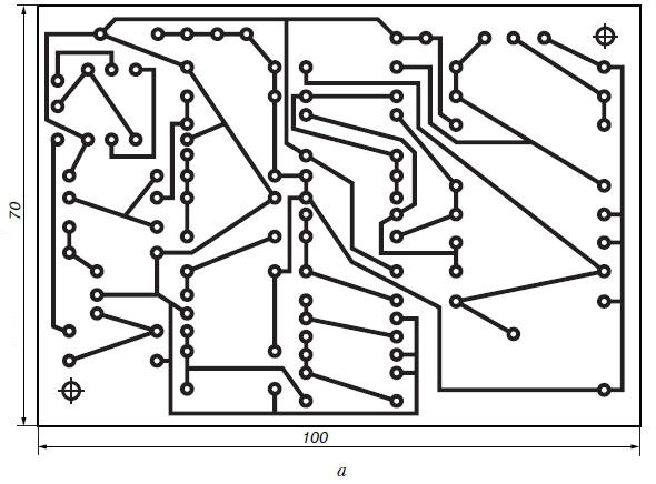
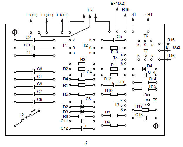
Fig. 2.11. Printed circuit Board (a) and the arrangement of elements (b) of the metal detector with high sensitivity
In amplification stages (transistors T3, T4 and T5) instead of type transistors CTB you can install type transistors CTG, CTA or CTA - CTA. Transistor type CTA (T6) is to replace KT361, and the transistor type CE (T7) - KT315 with any alphabetic indices. But in this case, the headphones should be high resistance (type TONE-2 or TAG-1). When using low impedance phones the transistor T7 has to be more powerful, such as the type CTB or CTB.
As the Zener diode D1 is also possible to use a Zener type D-D or CSA. Diodes D2 and D3 can be any of series D1, D9 or D10. The coil L2 has 250 turns of wire sew-2 0.1 mm in diameter, wound on the yoke SAT-23-11a. During manufacture it is possible to use other cores. It is important that the inductance of the finished coil was 4 mg.
The measuring coil L1 contains 100 turns of PEV-1 with a diameter of 0.3 mm and made in the form of a torus with a diameter of 160 mm. This reel is easier to produce hard the frame, however, you can do without it. In this case, as a temporary the frame may be any suitable size round object, for example the Bank. The turns of the coil are wound in bulk, and then removed from frame and screened electrostatic screen, which is a open-loop tape made of aluminum foil, wound on top of the harness turns. Crack between the beginning and the end of winding of the tape (the gap between the ends of the screen) should be at least 10 mm.
In the manufacture of the coil L1 must be careful to avoid the closure ends of the shielding tape, as in this case, is formed closed loop. To increase the mechanical strength of the coil can to impregnate with epoxy glue.
To the terminals of the coil should be soldered conductors double-shielded cable length of about one meter, at the other end of which fits the socket type SS-3 or any other suitable small-sized connector. The braided cable is necessary to connect with screen coil. In the working position coil connector connects to mating connector located on the housing of the device.
The power to the detector sensitivity is performed from the source B1 voltage of 4.5 V. as such a source can be used, for example, the so-called square battery type 3336L or three element type 316, 343, are connected in series.
Printed circuit Board with the controls it contains and the power source are placed in any appropriate plastic or wooden case. On the housing cover set variable resistors R7 and R16, connector X1 for connection the search coil L1, a switch S1, and also connector x2 for connecting head phones BF1.
Establishing
As with the adjustment of other detectors, the configuration of this unit is to performed under conditions when metal objects are removed from the search coil L1 for a distance of not less than 1.5 m.
Direct the establishment of the detector should start with select beat frequency. It is recommended to use the oscilloscope or digital frequency meter. When working with the oscilloscope probe must be connected to the connection point resistors R1, R4, R5 and capacitor C8, that is, to the input of the detector. The waveform at this point resembles the waveform of the modulated RF signal. Further, adjusting the coil L2 and selecting the capacitance of the capacitors C2 and C6, you need to ensure that the frequency modulation (beat frequency) would be equal to about 10 Hz.
When using a digital frequency meter to adjust the metal detector frequency you should connect first to the collector circuit of transistor T1, and then to the collector of transistor T2. By changing the parameters of the previously listed items (the inductance of the coil L2, the capacitance of the capacitors C2 and C6), it is necessary to achieve the frequency difference between the signals at the collectors of transistors T1 and T2 was approximately 10 Hz.
Further, the selection of the resistor R8 is set to maximum gain cascade performed on the transistor T3. In the absence of the oscilloscope and the frequency selection of the desired beat frequency can to perform without them. When you do this, you must first install in the middle position the engine of the resistor R7, and then by turning the trimpot core of the coil L2, to achieve the emergence of phones in clicks with a frequency of about 1-5 Hz. If you need to install the frequency is not possible, you should choose the capacitance of the capacitor C6. To reduce the effects of the background soil, the final selection of the beat frequency should be when approaching the search coil L1 to the ground.
Thus, the process settings of the metal detector with high sensitivity ends.
The order of work
In practical use of this detector should be variable resistor R7 to maintain the desired frequency of the beat signal, which changed when the battery discharge, when the temperature of the environment or when the deviation of the magnetic properties of the soil. You also need to adjust the volume clicks using the slider R16.
If in the process of work in the area of the search coil L1 will be any metal object, the frequency of the signal in the phones will change. When approaching one metals the frequency of the beat signal will increase, and when approaching others will decrease. To change the tone of the beat signal, having some experience, you can easily determine the kind of metal, magnetic or non-magnetic, made detected object.
With such a detector small objects, such as nails, can be found under the layer of soil up to a depth of 10-15 cm, and large (for example cover wells) - up to a depth of 50-60 cm.
Author: M. V. Adamenko