


")

In metal detectors type BFO (Beat Frequency Oscillator) in which the reference and measuring the generators are assembled on the elements of one chip, there are some disadvantages. In the first all, they include the occurrence of parasitic relationships between individual elements inside the crystal chips, which are virtually eliminated impossible. That is why in such detectors have to choose the frequency beating more than 100-300 Hz, which inevitably leads to a reduction in the sensitivity device. Therefore, becoming more popular devices running on analyzing the beat signal in which the reference and measurement generators collected on separate chips.
Schematic diagram
The proposed device is a one of options type of metal detectors BFO (Beat Frequency Oscillator), that is, a device which based on the principle of analysis of beating the two signals close in frequency. In this design estimate changes in the frequency of the beats is by listening.
The basis of this device (Fig. 3.10) constitute the reference and measurement generators, matching the cascades, a mixer and a scheme of acoustic indication.
Fig. 3.10. Schematic diagram of the detector on three chips
In our structure as a reference and test oscillators used two simple LC oscillator. Circuit solutions these generators are almost identical. In this reference generator is assembled on the elements of the IC1.1 and IC1.2 of chip IC1 and the second, measuring or tunable, the generator performed on the elements of IC2.1 and IC2.2 of chip IC2. The working frequency of the reference oscillator is determined by the parameters of the elements, forming its oscillating circuit, that is, the capacitances of the capacitors C1, C3, C5 and C6, as well as the inductance of the coil L1. In the circuit of the measuring oscillator capacitors C2, C4, C7, C8 and search coil L2. Both oscillator tuned to an operating frequency of approximately 300 kHz.
Cascades performed on the elements of the IC1.3 and IC2.3, provide isolation between generators DC voltage, and also weaken the influence of the mixer in generators. From the outputs of buffer stages, the RF signals through the capacitors C11 and C12 are served on a mixer and then to the amplifier oscillations of the difference frequency, which are made on chip IC3. Then, the beat signal is fed to the headphones BF1. When the capacitor C15 provides filtering of high-frequency component of the signal.
Power to the chip is supplied from the source B1 with a 9 V through the filter, formed by the capacitors C16 and C17.
When approaching the search coil L2 tunable resonant circuit generator a metal object, its inductance is changed, which causes changing the operating frequency of the generator. If near the coil L2 is the subject of the magnetic metal, its inductance increases, which leads to reduction the frequency of the generator. Non-ferrous metal reduces the inductance of the coil L2, and the working the oscillator frequency increases. By changing the frequency of the beat signal in the head phones can be concluded about the appearance in the area of the search coil metal object, and to increase or decrease tone - what metal made detected object.
Details and design
All the details of the considered detector (with the exception of the search coil L2, connectors X1 and x2, as well as switch S1) located on the circuit Board size h mm (Fig. 3.11) made of one-sided glass Micarta or PCB.
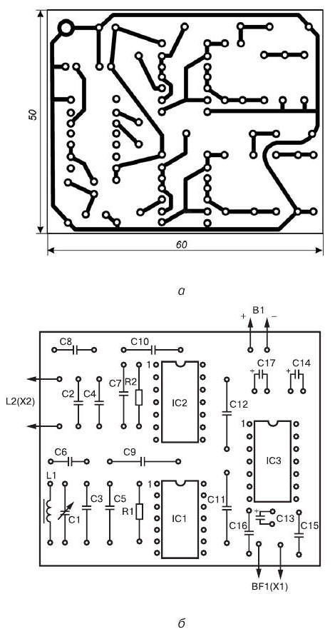
Fig. 3.11. Printed circuit Board (a) and the arrangement of elements (b) of the metal detector three chips
To detail used in this device without facing any special requirements. It is recommended to use any small-sized capacitors and resistors that can be placed on the circuit Board. In this case the fee is calculated on installation of fixed resistors type MLT-0,125 or other small-sized (e.g. MLT-0,25 or sun-0,125). Capacitors C2, C5-C7 and C8 can be type CT-1, capacitors C3, C4, C9-C12, C15 and C16 - type km-4 or K10-7V, and capacitors C13 and C17 - type K50-6.
As capacitor C1 is recommended to use any capacitor variable capacity from small-sized radio. You can use the trimpot type capacitors KPK-3 capacity of 25-150 pF. The maximum capacitance of the capacitor C1 shall be not less than 200 pF.
Coil L1 of the reference oscillator circuit formed on the frame from the ring magnetic type ND CHH and contains 50 turns of wire diameter pelsho 0.2 mm, which is evenly wound around the perimeter of the magnetic core.
The search coil L2 contains 50 turns of wire pelsho diameter of 0.27 mm and made in the form of a ring with a diameter of 180-220 mm. This reel is easier to make on a a rigid frame, but you can do without it. In this case, as temporary frame may be any suitable size round subject. The turns of the coil are wound in bulk, and then removed from the frame and for the purpose increase the mechanical strength of impregnated epoxy glue. Then coil L2 is shielded electrostatic screen, representing the open-loop tape from aluminium foil is wound on top of the harness turns. The gap between the beginning and the end winding of the tape (the gap between the ends of the screen) should be not less than 15-20 mm.
In the manufacture of the coil L2, it is necessary to ensure that did not happen the closure ends of the shielding tape, as in this case, a closed loop is formed. To protect from damage the foil can be wrapped one or two layers of electrical tape.
A source of audio signals can serve as high impedance headphones type TONE-2, TA-4 or similar.
As the power source B1 can be used, for example, the battery "Krona" or two batteries type 3336L connected in series.
Printed circuit Board with the controls it contains and the power source are placed in any suitable metal enclosure. On the housing cover installed: connector X1 for connection of headphones BF1, connector x2 for connecting search coil L2 and the switch S1.
Establishing
This detector should be set in the conditions, when the metal items removed from the search coil L2 at a distance of not less than 1.5 m.
Direct tuning of the instrument is to select the desired beat frequency. It is recommended to use an oscilloscope or a digital frequency meter. First, set the frequency of the reference oscillator by controlling its the value on pin 10 of the chip IC1. The frequency of the reference oscillator is set equal to approximately 300 kHz, the selection of the capacitors C5 and C6, and also, if necessary, adjust the core of the coil L1. Pre - the rotor of the capacitor C1 should be set approximately to the middle position. Next, selecting the capacitance of the capacitor C2, it is necessary to set the frequency of measurement generator by controlling its value at pin 10 of chip IC2. In this case the frequency of the measuring oscillator is selected so that its value differed the frequency of the reference oscillator of about 500-1000 Hz.
The configuration process of the device ends.
The order of work
Practical use of the considered detector has significant differences from the procedure of work with other devices BFO in which assessment of the presence of a metal object within range of the search coil is done by ear.
If in the process of work in the area of the search coil L2 will be any metal object, the frequency of the beat signal in the head phones will change. When approaching one metals the frequency of the signal will increase when approaching others to decrease. To change the tone of the beat signal, having some experience, you can easily determine the kind of metal, magnetic or non-magnetic, made the detected object.
Variable capacitor C1 is maintained at the necessary frequency of the beat signal, which can change under the influence of various factors (for example when changing the magnetic properties of the soil, the ambient temperature or battery discharge).
With the help of this device small objects (e.g. coin medium size) can be detected up to a depth of 60-70 mm, and a manhole cover on the 0.5 m depth.
Author: M. V. Adamenko