


")

Simple and at the same time reliable and effective metal detector BFO, working on the principle of assessment of changes in the frequency of the beat signal, it is possible to collect all on a single chip CLP.
Schematic diagram
A distinctive feature of the considered metal detector is not only the use of chip type CLP, but also circuit solutions used in the development of generators and analyzer (Fig. 3.8). In this structure, the change in frequency signal beats is by listening.
Fig. 3.8. Schematic diagram of the detector on the chip CLP
The basis of this device constitute reference and measurement generators, mixer scheme and acoustic indication.
In this design used two simple LC oscillator, performed on the elements of the chip IC1. Circuit solutions these generators are almost identical. The first generator, which is the support is assembled on the element IC1.1, and the second, measuring or tunable generator configured on the element IC1.2.
The working frequency of the reference oscillator is determined by the parameters of the elements, forming its oscillating circuit, that is, the capacitances of the capacitors C1 and C2, and also inductance coil L1. In the circuit of the measuring oscillator is used, the capacitor C4 and the search coil L2. Both generator tuned to the operating frequency approximately 100 kHz. When approaching the search coil L2 tunable resonant circuit generator a metal object, its inductance is changed, which causes changing the operating frequency of the generator. In this case, if near the coil L2 is the subject of black metal, its inductance increases, which leads to reduction of the frequency of the generator. Non-ferrous metal reduces the inductance of the coil L2, and the operating frequency of the generator increases.
From the outputs of the generators of HF oscillations serves to corresponding inputs of the mixer, performed on the element IC1.3 (conclusions IC1/5,6). The load of the mixer is the resistor R5, which simultaneously acts as a volume control. Then the low-frequency signal through the resistor R6 and capacitor C8 acts on amplifier bass collected on the element IC1.4, and then to the headphones BF1.
Power to the chip IC1 is supplied from the source B1 with a 9 V through the filter, formed by capacitors C10 and C11.
Details and design
All the details of the considered detector (with the exception of the search coil L2, resistor R5, connectors X1 and x2, as well as switch S1) is placed on the PCB size 50x50 mm (Fig. 3.9), made of one-way foil Micarta or phenolic resin.
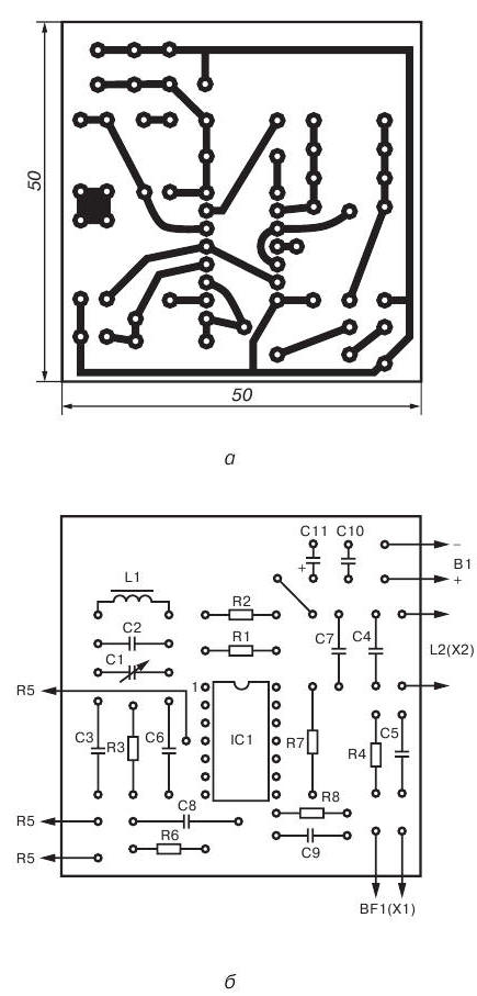
Fig. 3.9. Printed circuit Board (a) and the arrangement of elements (b) of the metal detector on a chip CLP
To detail used in this device without facing any special requirements. It is recommended to use any small-sized capacitors and resistors that can be placed on the circuit Board. In this case the fee is calculated on installation of fixed resistors type MLT-0,125 or other small-sized (e.g. MLT - 0,25 or sun-0,125). Capacitors C2-C7 can be type CT-1, capacitors C8-C10 - type km-4 or K10-7V, and the capacitor C11 type K50-6.
As capacitor C1 is recommended to use any capacitor variable capacity from a compact radio receiver (such as a transistor receiver "World"). You can use trimmer capacitors type PDA-3 capacity of 25-150 pF. The maximum capacitance of the capacitor C1 should not be less than 150 pF.
Variable resistor R5 can be any small, however, as such a the regulator is not recommended to use resistors, mechanically connected with the power switch S1.
Coil L1 of the reference oscillator circuit formed on the frame from the ring magnetic type ND CHH and contains 180 turns of wire diameter pelsho 0.14 mm, which is evenly wound around the perimeter of the magnetic core.
The search coil L2 has 100 turns of wire pelsho diameter of 0.27 mm and made in the form of a ring with a diameter of 230 to 250 mm. This reel is easier to make on a a rigid frame, but you can do without it. In this case, as temporary frame may be any suitable size round subject. The turns of the coil are wound in bulk, and then removed from the frame and with the purpose of increasing the mechanical strength of the impregnated epoxy glue. Then coil L2 is shielded electrostatic screen, representing unconfined tape aluminum foil is wound on top of the harness turns. The gap between the beginning of and the end of winding of the tape (the gap between the ends of the screen) should be at least 15-20 mm. In the manufacture of the coil L2, it is necessary to ensure that not there was a short circuit ends of the shielding tape, as in this case, a closed loop is formed. To protect from damage the foil can be wrapped one or two layers of electrical tape.
A source of audio signals can serve as high impedance headphones type TONE-2, TA-4 or similar.
As the power source B1 can be used, for example, the battery "Krona" or two batteries type 3336L connected in series.
Printed circuit Board with the controls it contains and the power source are placed in any suitable metal enclosure. On the housing cover installed variable resistor R5, connector X1 for connection of headphones BF1, connector X2 for connecting the search coil L2 and the switch S1.
Establishing
This appliance should be set up in conditions when metal objects removed from the search coil L2 at a distance of not less than 1.5 m.
Using frequency meter or oscilloscope, you must configure the operating frequencies reference and test oscillators. The frequency of the reference oscillator is set equal to about 100 kHz, the selection of the capacitors C2 and need adjustment the core of the coil L1. Pre-rotor capacitor C1 should be set approximately to the middle position. Further selection the capacitance of the capacitor C4, the frequency of the measuring oscillator is selected so that its value differed from the reference oscillator frequency of about 500-1000 Hz.
The configuration process of the device ends.
The order of work
In the practical use of this device is a variable capacitor C1 to maintain the desired signal frequency of the beats, which can change under the influence of various factors (for example when changing the magnetic properties of the soil, the ambient temperature or battery discharge).
If in the process of work in the area of the search coil L2 will be any metal object, the signal frequency will change. When approaching among metals, the frequency of the beat signal will increase when approaching others will decrease. To change the tone of the beat signal, having some experience, you can easily determine the kind of metal, magnetic or non-magnetic, made detected object.
With the help of this device small objects (e.g. coin medium size) can be detected up to a depth of 50 mm, and a manhole cover on the depth to 0.4 m.
Author: R. Ceteris