This detector is based on the principle of changes in the beat frequency of the two generators. Scheme his work is simple: the signals from search and reference generators come in a mixer, forming the output signal of the differential frequency. When approaching the metal to the search coil of the generator changes frequency, and consequently the difference frequency relative to the reference generator, lying typically in the audio range.
At first glance it seems obvious that the sensitivity of the detector more, the higher the frequency of its generators. Actually it is not. With increasing frequency increases the absorption of electromagnetic waves by the soil. Therefore, it becomes harder to get rid of unwanted self-synchronization generators at the expense of communication through the supply circuit and the parasitic capacity of the installation.
Besides the random fluctuations in the frequency of the search oscillator reach values, comparable with the changes in frequency caused by the proximity of metal items.
Finally, only at very low (tens of kHz) operating frequency can remotely to distinguish between ferrous and non-ferrous metals. The presence of metal it holds to change the phase difference of oscillations and search reference generator, synchronized with the loop PLL. The search is performed in dynamic mode with a repetition period of sweeps of the sensor approximately 1 sec.
This detector is able to distinguish between metals on the basis of BLACK/COLORED.
Schematic diagram
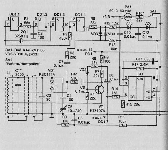
Schematic diagram of the detector shown in Fig. 2.10. Reference oscillator made on the chip DD1, its frequency 32768 Hz stable quartz resonator ZOl.
The signal of this oscillator is fed to the mixer VD3VD4 through a resistive divider voltage R6R13.
Search generator made on the transistor VT1. Coil L1 serving sensitive element of the detector is connected to the generator four-wire shielded cable. The feedback signal from the tap of the coil is supplied to the emitter of the transistor VT1, and the chain R6C7 - on the mixer.
Controls the frequency of the search oscillator VD1 voltage-variable capacitor. Chain R13C10 and R17C11 provide additional filtering, reducing the level of high frequency components at the output of the amplifier DA1.
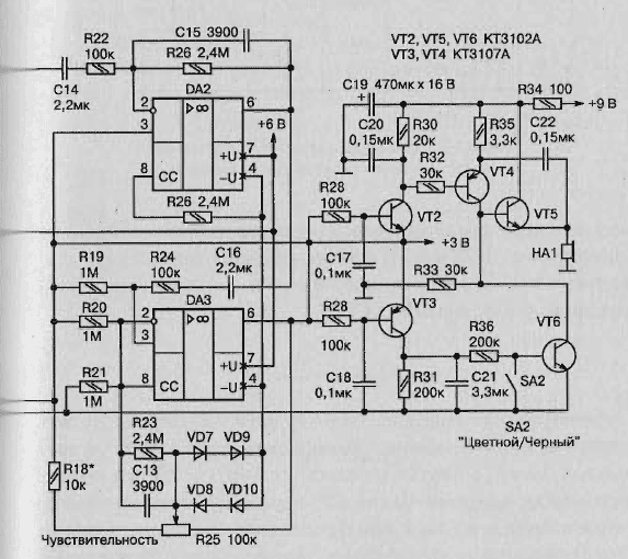
The sensitivity of the detector is adjusted by the variable resistor R25. Diodes VD7-VD10 prevent an overload of the amplifier DA3 at disrupting synchronization generators during configuration of the device or when it detects large metal items.
During passage of the gauge of the metal detector over the subject of non-ferrous metal, having ferromagnetic properties, the output of op-amp DA3 surge occurs the signal is first positive and then negative polarity.
Positive half wave opens the transistor VT2, which includes sound generator transistors VT4 and VT5. If the subject has ferromagnetic properties, the surge has the opposite polarity. His first (negative) half wave opens the VT3 transistor, whereby the capacitor C21 charging. The transistor VT6 is opened, and the time required to discharge capacitor C21 through the resistor R31, shunt resistor R33 - collector the load transistor VT5, thus, prohibiting the sounding of an audible signal under the second (positive) half-wave signal.
This happens when the contacts of the switch SA2 open ("COLOUR METAL"). When the closed contacts (position "BLACK METAL") sound indication work and upon detection of the subject of iron or steel, but only after the passage over it of the coil sensor.
Microammeter RA1 with an additional resistor R16 serves as a voltmeter, which measures constant (switch SA1 in position "OPERATION") or a variable (in position "SETTING") component of the voltage at the output of DA1. The first allows you to specify the position of the detected object, the second is to lock the synchronization points generators and its breakdown.
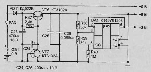
Schematic diagram of the power node
In Fig. 2.11 shows a diagram of the node power detector. A voltage of +9 V to power the audible alarm is removed directly from the battery GB1 (if enclosed switch SA3). Voltage stabilizer +6 In for supply of major components of the assembled detector transistors VT7 and VT8, and the first of them serves as a Zener diode. Artificial "mid-point" (chain +3 V) created using OS DA4.


Fig. 2.10. Schematic diagram

Fig. 2.11. A schematic diagram of a node of elf power metal detector
Design and details
The basis for the manufacture of the sensor coil L1 can serve as a thin-walled aluminium pipe outer diameter 14 mm, bent into a ring with a diameter of 250 mm with the gap between the ends of 10 mm around the perimeter of the outside of the ring with a hacksaw or the cutter needs to make the cut. Through it inside the pipe will be laid turns of the coil L1 (wire PELSHO of 0.3). The number of turns of 25+55 + 120, ranging from the earthy end.
In the winding process every 2-3 turns of wire should be lubricated epoxy resin. The tube cavity of the finished coil should be filled with silicone sealant and cover the entire structure of nitro.
Close the gap to the ring must be screwed Board with glass fibre laminate contact pads to which solder:
- the terminals of the coil;
- the capacitor C1;
- wire connection cable.
Under one of the ends of the pipe in the place of attachment to the PCB should enclose metal petal to which to solder the braided shield output the connecting cable.
After settings of the metal detector this entire site to protect from moisture should be covered with a plastic box or fill with silicone sealant.
The coil is best to install on a wooden cross, in the Central part which make the plastic "ears" for connection with telescopic boom a dielectric material. Fee with the basic details of the metal detector needs to be placed in a metal housing mounted on the opposite coil the rod end.
Contour capacitor C1 composed of several connected in parallel capacitors K71-7 with a total capacity equal as indicated on the diagram. You can apply and other thermostable capacitors (groups TKE M47 or M75). The transistor VT7 should be selected with a breakdown voltage emitter junction of 6.2 to 6.5 V. the other elements of the scheme specific requirements.
Variable capacitor C5 from a transistor radio. Quartz the resonator ZQ1 - hour. Micro - ammeter PA1 - with a zero in the middle of the scale. A series resistor R16 are selected so that when voltage of +2.5 V and -2.5 In the needle of the microammeter deviated to the appropriate end of the scale.
As HA1 tested various projectors. Most suitable was a Cup of TEMP-311 with a coil resistance of 250 Ohms. When the intake sound generator current is not more than 3 mA alarm volume is quite sufficient. If you use high impedance headphones, the current consumption can be further be reduced.
Author: L. Jugaran


