


")

In the first half of the 70-ies of the last century in the Soviet Union was developed and serially produced a metal detector MI-2, which is widely was used in the national economy. The layout and design of this device repeatedly refined and improved. One of the known variants metal detector MI-2 can be recommended for beginners for radio Amateurs repetition.
Schematic diagram
Metal detector MI-2 represents one of numerous variants of the device type BFO (Beat Frequency Oscillator), that is, a device, based on principle of analysis the beating of the two frequencies. Thus in this design assessment changing the frequency is done by ear (Fig. 2.12).
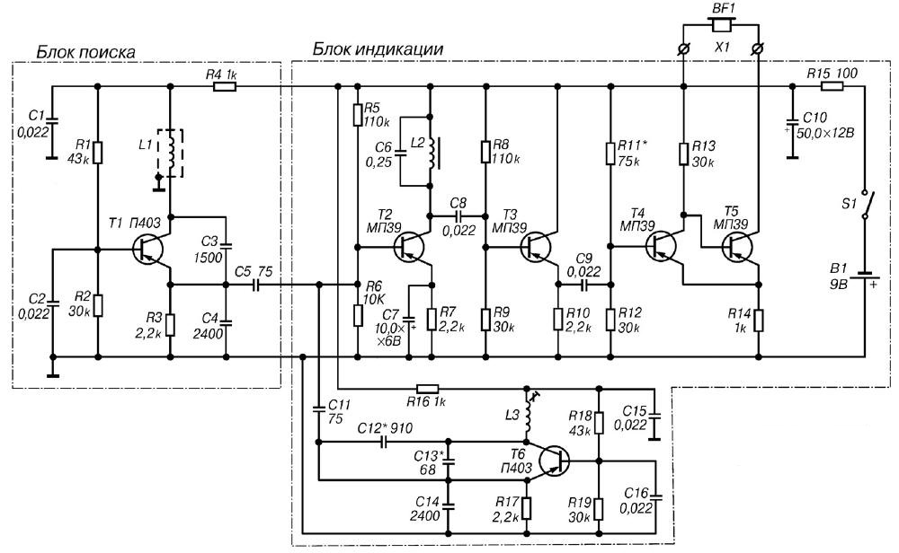
Fig. 2.12. Schematic diagram of the detector MI-2 (click to enlarge)
The basis of the scheme of the instrument are measuring and reference generators, capacitive cascade, emitter follower, Schmitt trigger and head phones. The measuring generator is performed on the transistor T1, connected in the circuit with common base. Operating frequency of this oscillator is determined by the parameters of the oscillatory circuit, which consists of the search coil L1 and capacitors C3, C4. The feedback voltage required for excitation, served with the collector of transistor T1 in the emitter circuit through the capacitive divider C3, C4. In the result of the output of the measuring oscillator is formed sinusoidal signal frequency is 510 kHz.
Reference oscillator is made on the transistor T6 by a scheme similar to the scheme measuring generator. Operating frequency of this oscillator is determined the parameters of the oscillating circuit, which consists of a coil L3 with brass trimmer core and capacitors C12, C13 and C14. Fluctuations from the reference and test oscillators through capacitors C5 and C11 is input to the mixer, which is made on the transistor T2. The collector the circuit of the transistor T2 included circuit consisting of a coil L2 and capacitor C6, in which stand the fluctuations of the difference frequency.
The search coil L1, part of the resonant circuit measuring generator is a sensor responsive to the appearance in the zone of action of the device metallic objects. When approaching the coil L1 subject to such changes it inductance and, consequently, changing the frequency of the measuring signal generator. As a result, the frequency of the signal at the output of the mixing cascade also will change. Since the mixer circuit, performed on the elements of L2 and C6, tuned to the difference frequency of the oscillations of the measuring and the reference generator in the absence of metal objects, changing the frequency of the signal and will lead to decrease of the amplitude of the signal at the mixer output. The working frequency of the circuit mixer is 1 kHz.
Next, the selected signal is fed to the emitter follower made on the transistor T3 and serves to harmonize the Schmitt trigger with mixer tap. The Schmitt trigger transistors T4, T5 and is an e relay responsive to the change in the amplitude of the input signal. Modes of operation transistors T4 and T5 are selected so that the trigger is triggered when the voltage of the input signal is more than 0.5 V. the Generated acoustic signal served on the headphones BF1.
Food metal detector is from the source B1 voltage of 9 V, with consumption current does not exceed 4-5 mA.
Details and design
Structurally, the detector MI-2 consists of two blocks. The module search includes items forming the measuring generator, the unit indication - reference generator capacitor stage, the emitter follower and Schmitt trigger. Both units are connected by a shielded cable.
It is used in the Assembly of the detector MI-2 parts are not made any special requirements. The only restriction is associated only with dimensions since most of the components of the device mounted on two relatively small printed circuit boards.
The details of the search block is placed on the PCB size h mm, made of one-sided glass Micarta or fiberglass (Fig. 2.13).
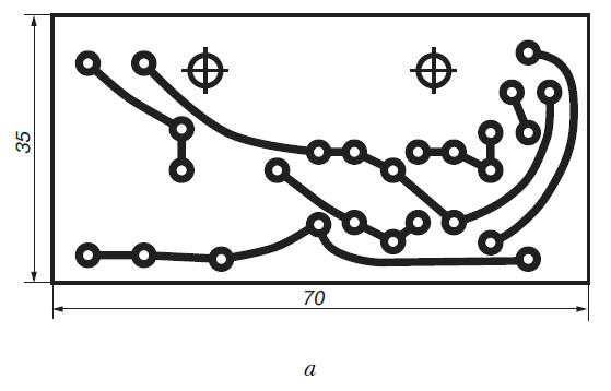
Fig. 2.13. The printed circuit Board unit search metal detector MI-2 (a) and the location the elements on it (b)
The details of the display unit placed on the PCB size h mm, also made of one-sided foil Micarta or fiberglass (Fig. 2.14).
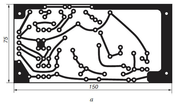
Fig. 2.14. The printed circuit Board of the display unit of the metal detector MI-2 (a) and the location of elements on it (b)
In the metal detector produced serially MI-2 was used type resistors MLT- 0,125, capacitors C1, C2, C8, C9, C15 and C16 - type KLS-1; C5, C11, C13 - CSR-1; capacitors C3, C4, C12, C14 - type CSR-2; C6 - MBM or MBM-2; electrolytic capacitors C7 and C10 - type K50-3. Naturally, when the repetition of this device, you can use any similar items from modern element base. As the source of the acoustic signal suitable headphones type TONE-1.
The search coil L1 is made in the form of a ring with a diameter of about 300 mm. Coils the coils are enclosed in an electrostatic shield from dural tube diameter 8 mm and a wall thickness of 1 mm. For the manufacture of coils you need to make the harness of ten pieces of PEV-2 in diameter of 0.96 mm and a length of 1250 mm. First harness you need to push through a PVC pipe with a length of 1000 mm, and then in dural tube of length 960 mm Dural tube with her the wires should be bent according to the template in the ring. As the screen can to use regular aluminum foil. Wire pieces are connected consistently using desoldering on the block, installed in the housing block search.
In the manufacture of the coil L1 must be especially careful to ensure that not there was a short circuit ends of the shielding tube, as in this case closed loop is formed. Therefore, the ends of the screen it is desirable to isolate a rubber tube. The coil L2 of the mixer is wound on an annular ferrite core M2000 NM-A-Khh. It has 200 turns of wire sew-2 with a diameter of 0.47 mm and mounted on the circuit Board of the display unit.
Coil L3 contains the reference oscillator 135 turns of wire of diameter 0.1 PALSO mm, which wound up on the frame with a diameter of 7-9 mm podstreshny core, made of brass. If necessary, with a detailed description of the special the design of the coil L3 can be found in the magazine "Radio", No. 4, 1973.
The block search is made of duralumin. The search coil L1 and the block search fixed to the bottom of a special pen. The housing of the display unit also made from duraluminum. On the housing cover mounted connector for connection block search (on the concept is not specified), the switch S1, and also connector X1 for connection of headphones BF1. The cover also has to be the hole for the knob of the coil L3. As the power source B1 can be used, for example, two batteries 3336L connected in series.
Establishing
The main steps in the establishment of the detector MI-2 are threshold setting actuation of the trigger and the choice of the reference oscillator frequency.
The threshold trigger is set using the selection of resistance resistor R11. To do this, unsolder from the collector of the output transistor T2 capacitor C8 and to apply for this capacitor is the signal from the sound generator a voltage of 0.5 V at a frequency of 1 kHz. The resistance value of the resistor R11 it is necessary to choose such that, under a slight decrease in the amplitude sound generator the sound in the head phones disappeared, and the collector current transistor T5 has become equal to zero.
Coarse tuning of the frequency signal generated by a local oscillator running the selection of the capacitance of the capacitor C12. More precisely the frequency value is set the selection of the capacitance of the capacitor C18. These adjustments should be carried out in conditions when metal objects removed from the search coil L1 at a distance of not less than 1.5 m. the Frequency of the reference oscillator is determined by the frequency or oscilloscope. When the capacitor C11 must be sealed from the emitter transistor T6.
You must then set the center frequency of the reference oscillator. For this to restore the connection of the capacitor C11 to the emitter of the transistor T6. the search block to disconnect from the display unit and a frequency counter to measure frequency the reference oscillator with the setting knob of the coil L3 in the extreme position. The average frequency of the reference oscillator is defined as the average arithmetic mean values of the measured frequencies. If necessary, the size of containers capacitors C12 and C13 are selected so that the average frequency of the reference generator different from the frequency of the measuring oscillator at 1 kHz.
After adjusting the frequencies of the measuring and reference generators rotate the tuning core coil L3 at the output of the mixing cascade must be set the voltage level of the signal a bit more than 0.5 V. In this case with a frequency of the incoming signal of the trigger switch, and in the head phones will be an alarm sounds.
The order of work
Conduct prospecting using a metal detector MI-2 does not have any features. If the area of operation of this device will be metal the subject, when you approach it the search coil L1 in the head phones to listen to the tone of varying frequency, falling volume. If coil even closer to the metal object, the voltage signal on the mixer output becomes less than the threshold of the trigger. The trigger stops switch and alarm sound in the head phones will disappear.
Optionally, the search can be done tuning the metal detector at the beat frequency by adjusting the position of the core of the coil L3.
In accordance with the data obtained in the practical use metal detector MI-2, large metal objects (for example, the pit cover) can be detected at a distance of 600-800 mm, small (e.g., a screwdriver) distance of 70-100 mm, and the coins of medium size, the device begins to react with distances of 30-50 mm.
Author: M. V. Adamenko