


")

Design features
This detector is an improved version of the detector, based on the comparison of frequencies of two oscillators, one of which is the reference , and second search and changes the frequency of its oscillations when approaching metallic objects. The device can "distinguish" non-ferrous and ferrous metals.
Schematic diagram
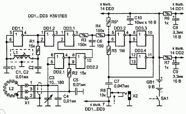
Reference oscillator assembled on the element DD1.1, and search on the elements DD2.1 and DD2.2. The oscillation frequency of the reference oscillator, defined by its contour data coil L1 and capacitors C1 and C2, and when these values is 100 kHz (Fig. 2.14). The frequency of the search oscillator, resonant circuit formed by remote the coil L2 and capacitors C3-C5, close to the frequency of the reference oscillator. It smoothly change the variable capacitor C3 within one to two kilohertz.
The element DD1.2 performs the function of the cascade, which serves to interchange between generators DC voltage. Chip DD1 and DD2 of the metal detector powered by a DC source GB1 through decoupling filters R6C8 and R7C9.
Element DD3.1 - the mixer signal generators. At the output are formed oscillations with sum and difference frequencies of the generators and their harmonics. For the selection differential signals, i.e., sound frequency is low frequency (LF) R3C6. Such circuit construction of the metal detector allows you to get the beats generators a frequency of several Hertz.
To provide listening for signals of such low frequencies on headphones used converting sinusoidal or rather, a triangular signal in short pulses at twice the frequency. This is achieved by using the voltage comparator collected on elements DD3.2 - DD3.4.
For one period of the beat frequency twice comparator switches from one logical state to another. It generates rectangular pulses differenzierte chain C7R8. So the phones connected to the connector x2, receives short pulses voltage and the volume of the audio signal not only depends on its frequency.
In phones that can be both high impedance and low impedance, heard "clicks". The volume of their regulate a variable resistor R8 (it is combined with power switch SA1).
The design of the metal detector
All parts except the plugs and contour search coil of the generator, you need to place on the PCB of bilateral foil material (Fig. 2.16). Installation of one - sided-from the printed conductors. Foil the other hand, that is the Board's edges connected to the common supply lead role performs screen.
Circuit Board and power source (battery "Emery") in a better place metal housing of appropriate size, for example, close of the plates glass epoxy. If the case will serve as a plastic box, it is the Board's edges, as well as in the positions indicated in Fig. 2.16 dashed lines should be soldered vertically strips of copper foil with a width of 7-10 mm.
Element base
Chip K561JIE5 can be replaced by K176JIE5, CLA, CLA. Capacitor Sz - KP-180 or the other, with a maximum capacity of 180 to 240 pF. Capacitors C8-XIU - oxide K50-6 or series K52, K53, rest km, KLS.
Fig. 2.16. PCB metal detector high sensitivity
Resistor R8 - CP3-3V, and the rest - sun, MLT. Connectors X1 and x2 is any small-sized.
Fig. 2.17. Remote coil
To improve the thermal stability of the capacitors C1, C2, C4 and C5 should be used with TKE is not worse MI500.
The search coils manufacturer
Coil L1 containing 300 turns of wire sew-2 0,08 must be wound on the frame of the inverter circuit of the radio "Climber-407".
The external search coil L2 of the generator (Fig. 2.17) is recommended such sequence:
- mandrel diameter 240-250 mm wound 30 turns of wire sew-2 0.6 mm;
- the resulting bundle to seal in 10-12 places a thin strong thread;
- heating coil over the flame of a gas stove to a temperature of 50-60 °With, to impregnate epoxy resin;
- after curing of the resin coil winding varnished cloth or (in extreme cases) insulation tape;
- the finished coil to saarnisaari, wound with thin copper foil with such that in the front there was a small, 5-10 mm long, unclosed section of the screen coil (you can certainly use and aluminum foil);
- ready remote coil and the screen is connected (through a connector (XI) with the design metal detector, shielded two-wire cable.
Adjustment of the metal detector
The establishment of the detector should begin with the setting of the reference oscillator and verify that the voltage comparator. For this purpose the rotor of the capacitor NW to position average capacity and podstroechnik coils L1 to change the reference oscillator frequency until the phone beeps. Then the same podstroechnik should strive for "zero beat" - "clicks" in phone, following with a frequency of several Hertz.
Sometimes, achieving this is not possible. The reason for this can be a problem in the comparator. In this case, it is necessary to check the performance of the rest of the device is to the output of the element DD3.1 to connect a high impedance phone (for example, TONE-2) and the same the podstroechnik coils L1 to achieve a sound signal.
Otherwise, you have to find an error in the installation of generators or faulty details. Comparator configuration is selecting a resistor R9 shown in Fig. 2.15 dashed lines. The resistance may be in the range of 300 ohms 1… IOM.
If the output of the comparator (pins 10, 11 of the chip DD3) high voltage level, we include this resistor between pins 5 and 6 of the element DD3.2 General wire. After setting the reference oscillator podstroechnik coil L1 must lock into the frame with a drop of glue.
For the convenience of working with a metal detector its discharge coil is best to provide a wooden or plastic handle. You can also make some remote coils of different diameter.
Author: Aleksandrov I.