Advantages and disadvantages
The principle of operation of all these devices is based on the comparison of the values of the frequency oscillations of the two oscillators:
- reference;
- search of changing the frequency when exposed to its resonant circuit metal object.
There are other methods:
- pavement, is logged when the unbalance of the measuring bridge, one arm of which included the search coil;
- method of phase shift when measured phase shift of the oscillations of the support and search generators.
- method of transmitter-receiver, where the re-radiated by the registered subject radiofrequency energy.
They are more efficient than the method of comparison of frequency values (method of beating). But he more simple to implement. Constructed using metal detectors have such advantages:
- they are compact;
- does not require careful tuning and measures high frequency stabilization;
- unpretentious in operation.
Therefore, they are widely spread in domestic and craftsmen radio Amateurs.
A schematic diagram of a simple metal detector
The device can be detected half dollar coin at a depth of 80 mm, and the cover sewer pit at a depth of 0.8 m.
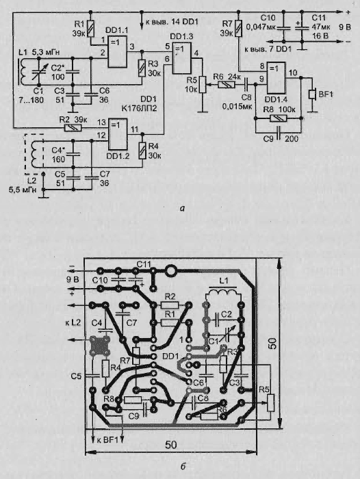
Schematic diagram of the simplest detector is depicted in Fig. 2.6, and. It assembled only a single chip CLP. One of its elements (DD1.1) used in the model generator, the other (DD1.3) tunable.
Oscillation circuit reference generator consists of a coil L1 and capacitors C1 and C2, and a search from the search coil L2 and capacitor C4. The first circuit rebuild in frequency by a variable capacitor C1 and the second a selection of capacitor C4. On the element DD1.3 is a mixer oscillation model and variable frequencies.
With the load of the node of the variable resistor R5, the difference frequency signal is input to the element DD1.4, and the amplified voltage of audio frequency - on the headphones BF1.
Schematic diagram of the detector sensitivity
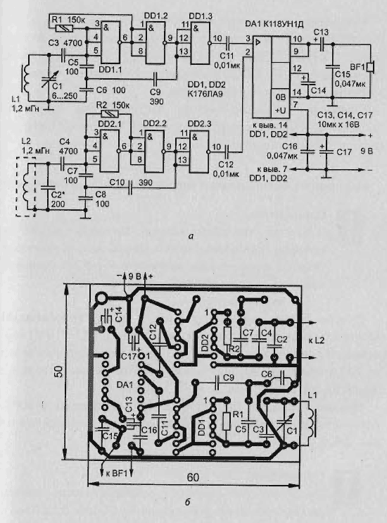
Consider a metal detector of high sensitivity, which is presented on Fig. 2.7, and. It as a mixer and amplifier oscillation the difference frequency applied to the chip COD (DA1).

Fig. 2.6. The simplest metal detector on the chip with the scheme of comparison: - schematic diagram; b - printed circuit Board

Fig. 2.7. The detector sensitivity on the chip with the circuit comparison: a - schematic diagram; b - printed circuit Board
Reference and search generators of this device is identical to the scheme. Each of them formed on the two inverters (DD1.1, DD1.2 and DD2.1, DD2.2, respectively). The elements DD1.3 and DD2.3 work as a buffer, weakening the influence of the mixer in generators.
Reference oscillator set to the frequency variable capacitor C1, and search a selection of capacitor C2.
Streamlined diagram of the detector on the beat
To increase the sensitivity of the metal detector, which uses the method beats, by adjusting the reference oscillator frequency is 5-10 times greater than the frequency of the search oscillator.
In this scenario, you experience the beating of the oscillations of the reference oscillator and the nearest frequency (5-10-th) harmonic search generator. In this case, the detuning of all at 10 Hz leads to the increase of the oscillation frequency difference of 100 Hz.
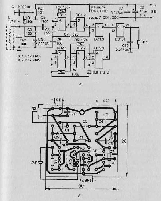
This method achieved a sensitivity of the metal detector, the scheme of which is shown in Fig. 2.8, and.
Half dollar coin with this detector can be found on a depth of 100 mm, and the lid of the well is at a depth of 1 m.

Fig. 2.8. Streamlined diagram of the detector on the beat: a - schematic scheme; b - printed circuit Board
The operation of the circuit of the upgraded detector
Reference oscillator of the detector is performed on two elements of the chip and DD2 tuned to the frequency of 1 MHz, the Required frequency stability is a quartz the resonator ZQ1.
In the search oscillator is used, the two elements DD1 chip. It oscillating circuit L1C2C3VD1 tuned to the frequency is several times smaller than reference oscillator.
For adjustment of the circuit is applied to the varicap VD1, the voltage at which regulate the variable resistor R2. The mixer is made on an element DD1.4, as buffers used elements DD1.3 and DD2.3.
Indicator search are head phones BF1.
Assembly and printed circuit Board
Each of the detectors can be mounted on a printed Board, of foiled fiberglass 1.5 mm thick. the Drawing Board and the arrangement of parts shown in Fig. 2.6 b, 2.7 b, 2.8 b, respectively.
Boards are designed for the installation of fixed resistors МJIT-OD (MLT-025, Sun-D), capacitors KT-1, km-4, or K10-7V, K50-6.
For the adjustment of the frequency generators applied to variable capacitors with solid dielectric from small transistor receivers:
- "The world" in the first device;
- "Planet" in the second device.
It is possible to use any other suitable dimensions and values the minimum and maximum capacitance, including trimming KPC-3 with a capacity of 25-150 pF.
The variable resistors R5 and R2 have any small type.
The coils of
Coil L1 for metal detectors collected by the schemes in Fig. 2.6 and 2.7, and, wound on ferrite (NN) annular magnetic conductor size K8 x 6 x 2.
In the first detector coil includes 180 turns of wire PELSHO 0,14, second 50 turns PELSHO of 0.2.
Winding in both cases - uniform around the perimeter of the magnetic core.
In the first detector coil is glued with glue BF-2 directly to print Board, and in the second (due to lack of space) - to a small area, closed from sheet of polystyrene with a thickness of 1.5 mm and glued the same adhesive to the Board.
The search coil so that each of the detectors is wound in a ring, bent from vinyl tubing with an outside diameter of 15 mm inner and 10 mm.
The outer diameter of the ring is:
- for the first scheme - 250 mm (100 loops);
- for the second and third to 200 mm (50 turns).
Applied wire - PELSHO of 0.27.
Each ring should be wrapped with a tape made of aluminum foil for electrostatic shielding to eliminate the effect the capacitance between the coil and ground. To protect from damage the foil preferably wrap one or two layers of electrical tape.
When winding the tape should be remembered that the electrical contact between its ends invalid (otherwise it is a vicious spiral).
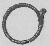
View the finished coils are manufactured using the described method, is shown in Fig. 2.9.

Fig. 2.9. Finish the search coil
With decreasing diameter of the search coil "capture area" narrows, but the device becomes more sensitive to small objects. With increasing diameter, on the contrary, the "capture zone" is increased, and the sensitivity to smaller objects reduced.
To display search in all the devices used head phones TONE-2. Nourish metal detectors can be from one battery "Krona" or from the United consistently two batteries 3336 or six elements 316, 332.
Author: R. Ceteris


