The metal detector is suitable for searching metal objects in the ground. It can also be used when determining the location of the reinforcement strip and hidden wiring during construction works in the house.
Schematic diagram
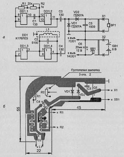
Diagram of compact metal detector on the chip type K175JIE5 shown in Fig. 2.1, and. It contains two oscillators (reference and search). Search generator assembled on the elements DD1.1, DD1.2, and the support - on the elements DD1.3 and DD1.4.


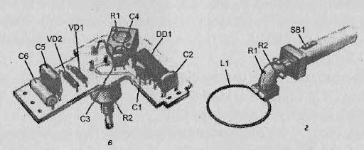
Fig. 2.1. Compact metal detector on the chip CLE: a - schematic scheme; b - circuit Board; - the placement of elements; g - General view of the device
The frequency of the search oscillator is made on the elements DD1.1 and DD1.2, depends on:
- from the capacitance of the capacitor C1;
- the total resistance of the trimpot and variable resistors R1 and R2.
The variable resistor R2 gradually changing the frequency of the search oscillator in the frequency range established by adjusted by the resistor R1. The frequency of the generator on the elements DD1.3 and DD1.4 depends on the parameters of the oscillating circuit L1, C2.
The signals from both generators are activated via the capacitors C3 and C4 to the detector, performed by the voltage doubling circuit of the diodes VD1 and VD2.
Load detector headphones are BF1, on which stands a difference the signal in the form of a low-frequency component converted headphones in the sound.
In parallel headphones switched capacitor C5, which bypasses them on high frequency. When approaching the search coil L1 to a metal object there is a change of the oscillator frequency on the elements DD1.3, DD1.4, as a result changing the tone of the sound in the headphones. On this basis and determine is in the search area metal object.
Used parts and substitutions of elements
Trimpot resistor R1 type SP5-2, variable resistor R2, spoo,5. Valid be used in circuits and other types of resistors, preferably small.
Electrolytic capacitor C6 type K50-12 - for a voltage less than 10 V. Other permanent capacitor type km-6. Coil L1 is placed in the ring with a diameter of 200 mm, a bent copper or aluminum tube with an inner diameter of 8 mm. Between the ends of the tube should be small insulated gap that was not closed loop. Coil wrap wire PELSHO of 0.5.
Through the tube must be routed in any way the maximum number of turns: the the more the merrier. As a headphone BF1 you can use head phones TONE-1, TONE-2. To power the detector uses battery type "Crown" or other types batteries with a voltage of 9 V. In the diagram of the detector chip CLI you can replace the chip CLA, CPU, CPU, CLA, CLA, K561LN2.
Mounting the unit
Parts of the device, in addition to inductors, power supply, headphones, and can be placed on the circuit Board, cut from foil fiberglass thickness of 1 mm (Fig. 2.1, b). You can use and other view of the PCB.
L-shaped form of payment is selected so that it can fit in the housing connector type SR.
To one end of the connector is attached to the handle of the metal tube and to the other the end by using adapter of insulating material is fastened metal the ring with the coil L1.
General view of the device shown in Fig. 2.1, g, and the placement of the elements of the device - in Fig. 2.1 V.
Setting
Before the commissioning of the detector setup and variable resistors need put in the middle position and close the contacts SB1. Dragging the slider a trick of the resistor R1, to achieve the lowest tone in the headphones.
When no sound should match the capacitance of the capacitor C2. When you are prompted malfunction of the detector should be soldered between pins 7 and 14 of the chip DD1 capacitor of 0.01 to 0.1 μf.
Author: Jaworski V.


