Low disk sensor is the complexity of its manufacture when the winding diameter of over 30 cm below cable sensor can be manufactured up to a diameter of 1.5 m. the Idea of this sensor is not new and is used as the sensor coil cut telephone shielded cable, bent in a circle and the corresponding way unsoldered. The rigidity of such a sensor is lower than disk, however, ease of fabrication justifies everything.
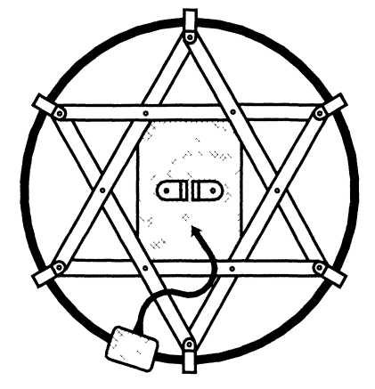
Unlike disk sensor cable the sensor has a negative buoyancy (sink in water), which is useful for underwater searches. In addition, cable gauge large diameter can be made collapsible! For the manufacture of the sensor shielded telephone cable brand CCI-30 or CCI-50, 30 or 50 pairs of wires, respectively. This cable will work winding, consisting of 60 or 100 turns. The appearance of the molded cable the sensor is shown in Fig. 38.

Fig. 38. Cable sensor
The sensor consists of a segment of the cable - winding 1, GRP 2 with braces vinyl plastic fasteners 3 to the winding 1, the junction box 4 and the cable 5. The design is clear from the figure, the explanation method only requires desoldering the cable and device connection boxes, and dwell.
To simplify desoldering the cable must first be familiar with some the specific nature of the device, which greatly simplify the matter. The conductors in the domestic cable industry (as in telephone cables many other types) retinue in pairs. One of the conductors of each pair is common and has either white or red insulation. Other conductors have colours: brown, yellow, green, blue, grey. Pairs are grouped in a cable by dozens, each dozen wrapped its viscose filament. Each dozen has five pairs of white common wire and five red. Thus, in each decile, each twisted a pair of wires with a unique combination of two colors.
Before you start to solder the ends of the cable, it is necessary to produce them accurately cutting (trained). The latter consists in dismantling the conductors of the cable dozens of pairs and within each ten.
Since the pitch of the twisting of each pair is sufficiently large (an ignorant person usually and ignoring that the conductors are twisted in pairs), for a successful takedown conductors need a free site (stock) a minimum length of 0.5 m each the end of the prepared cable cut.
The cutting end of the cable starting with Stripping, for which the necessary length make a circular incision of the outer plastic coating. Notching plastic need very carefully not to cut the inner cable conductor (especially uninsulated conductor that is output to the screen). After notching, centered in the notch (on a break) produce the plot Department external insulation with inner aluminum shield. For convenience, insulation it is necessary to remove lengths of 10...15 cm.
After removing the outer insulation and screen, but to unwinding of the protective film (!), it is necessary to secure the ends of all conductors (with adhesive tape or by twisting). Uninsulated shield wire of coils separately in a small the Cove, out of the way then it is possible to unravel the protective film and dismantle pair cable for dozens (each dozen wrapped its viscose filament)
Every top ten also fixed on the end of the sticky tape or twist after what bundles of a dozen possible to dissolve in the parties. While the cable is still "fresh" after end splitting, it is advisable to analyze every ten pairs. To do this, not freeing from fixing the end of one dozen, by its longitudinal and squeezing neat shaking and turning, seeking a "spilling" of the bundle of wires on twisted pair. As mentioned above, it is necessary to have a length the undressed portion of the cable is not less than 0.5 m.
The conductors in each pair are fastened to the end of a small piece of tape (for each pair). Additional labeling is not necessary, as in within each each pair, tens of unique combination of colors insulation. Then you can "ring out", i.e. to identify dozens on each the end of the cable, for example, by assigning them numbers (1, 2, 3 for 30-pair cable or 1-5 for 50-pair).
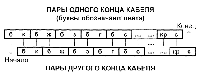
After this preliminary preparation, you can start soldering the conductors. The soldering should be carried out in several stages - dozens of pairs. In this case from each tens of twisted pair cable will work stand-alone section of the future winding sensor with 20 turns of wire. In the future, separate sections are included consistently-according to the formation of the winding with 60 or 100 turns. Pinout leads according to the diagram below.

Before soldering the ends of the conductors of the cable ends where the outer protective plastic insulation, as close as possible to each other. In this cable formed a circle of the required size. The cable and its ends secured in this position. In accordance with the proposed scheme selects one from dozens of conductors from one end of the cable, one on the other end. For example, the brown wire pair "white - brown" from one end and white wire a similar pair from another. The conductors are cut to a length of 5 cm, stripped from isolation, zalogovaya and fused together. The place of joint is sealed with adhesive tape or using a thin heat-shrinkable tube.
Thus Pinout produce pairs of every ten, and then solder tens among themselves. If you stick to the proposed scheme, in the end it should be winding with output beginning in the form of a wire with white insulation, and with the output end into the form of a wire with grey insulation.
After desoldering the winding point of adhesion of the ends of the cable placed in a plastic junction box dimensions 40x40x80 (mm). The internal volume of the box allows for small seal place we solder the ends of the 30 - or 50-pair cable. The internal volume of the box is filled with epoxy resin or epoxy glue. Fill ensures reliable additional insulation of the cable wires, protects them from breaking, and provides a solid mechanical connection the ends of the cable.
Within the junction box, the terminals of the winding of the sensor is connected to the end of the flexible cable passing through the hole in the box. The box also placed the capacitors of the resonant circuit of the sensor and other elements, if any provided by the scheme. Shown in Fig. 38 appearance conforms preformed design sensor cable with an outside diameter of 40 cm.
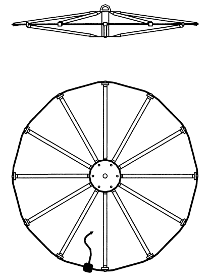
Cable, the sensor can be easily performed and a much larger diameter. The main limitation is the ability of the operator to manipulate such sensor at work, as well as the transportability of the sensor. The first limitation corresponds to the diameter of the sensor is not more than 1.5 meters and weights up to 5 kg. the Second restriction encourages to do construction cable sensor takedown. On Fig. 39 shows the construction of the collapsible cable of the sensor.

Fig. 39. Collapsible cable sensor
According to his principle of the proposed design recalls foldable design of the umbrella. The sensor comprises a cable ring terminal box of 12 fiberglass tubes-braces, 2 Central and auxiliary drives fastening elements. From the cable tube braces are attached using aluminum reduction sleeves mounted on the cable brackets and screws.
Adapter sleeves freely inserted inside the tubes of braces. Similar destination adapter sleeves are also on the Central disks (6 each). However, they are secured rotatably within a narrow range to tube braces could move during Assembly of the sensor the same way as move the spokes of an umbrella when it is opened. The circumference and length sensor tubes of braces are chosen so that in the assembled state of the cable winding the sensor was strong in tension (not less than 100 N). It should to take appropriate measures to prevent rupture and damage the windings sensor carefully follow the mechanical connection of the ends of the cable winding in ring in the connection box, to round off a sharp edge transition of the bushings in the points of contact with the cable winding of the sensor, etc.
Disassembled the sensor consists of separate elements: one ring cable with a fixed reduction bushings, 12 tubes-braces (they are easy be stored in a separate case), 2 Central disc and of the elements with by which the sensor is fixed in working condition - tightening screw nut, the Central thrust sleeve and carrying handles sensor or mounting node for interfacing with a barbell.
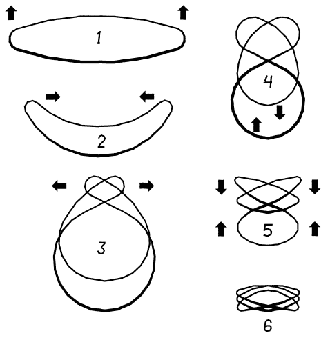
The particular trick is to fold the cable - winding of the sensor - in a disassembled state. The cable is flexible, but not to such much as a clothesline. He absolutely will not tolerate bends with small a radius of curvature and longitudinal torsion.
Any use of force when folding ring cable may lead to rupture inner foil screen and other damage!
The ring of the cable is folded in three turns. Sequence of operations for folding is shown in Fig. 40.

Fig. 40. The sequence of folding of the ring sensor cable
Author: A. I. Shchedrin


