The principle of operation
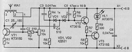
This original detector (Fig. 2.18) reacts to the approach of metal items to a magnetic antenna WA1. The antenna itself is part of the generator high frequency, performed on the transistor VT1. The oscillator frequency can to change a variable capacitor (capacitor used PDA-2 with change capacity from 25 to 150 pF).

Fig. 2.18. Schematic diagram metal detector
Schematic diagram
From the output of the generator high-frequency signal flows through the capacitor C4 to the rectifier (or detector), assembled on the diodes VD1, VD2. The voltage generated at the chain C5R6, opens the transistors VT2, VT3. HL1 led is lit. This state can be achieved by moving the engine variable resistor R3 from the bottom on the output circuit.
Approaching a magnetic antenna such as scissors, will cause such a change the frequency of the generator, the voltage on the base of the transistor VT2 will start to decrease. The led will extinguish.
Setting
Changing the frequency of the oscillator capacitor C1 and selecting the position of the slider variable resistor R3, it is necessary to achieve the greatest sensitivity detector - it will respond to a metallic object from a distance a few inches to a magnetic antenna. It may be possible to adjust the detector so that it can respond even to the approach of the hand.
In this embodiment, the oscillator frequency will change due to changes in the capacitance the oscillatory circuit of the generator.
Design
Magnetic antenna may be formed on the rod diameter 8 mm and length 80 mm ferrite NN. The coil must be wound in a single layer of wire sew-2 of 0.25. It should contain 83 loop with a branch from 9-turns, starting from output 1.
Author: I. Bakouchev


