


")

Here is the wailing alarm siren circuit diagram:
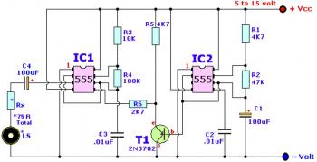
Components List:
R1,R5___________ 4.7K R2______________ 47K R3______________ 10K R4______________ 100K Rx______________ *see text C1,C4__________ 100uF/25V, electrolytic C2,C3__________ 0.01uF (10nF), ceramic T1_____________ 2N3702 (NTE159, TUP, etc.) IC1,IC2________ LM/NE555, MC1455P, etc LS_____________ Loudspeaker
This alarm circuit uses timer IC to generate frequency. The circuit has wide range supply voltage 5V to 15V DC.
*The Loudspeaker LS and the resistor marked “Rx” should be together 75 ohms. If you have a standard 8-ohm speaker then Rx is 67 ohms. The nearest value is 68 ohms. So for a 8 ohm loudspeaker Rx is 68 ohms. For a 4 ohm loudspeaker Rx is 71 ohms, for a 25 ohm loudspeaker Rx is 50 ohms, etc.
circuit diagram by Tony van Roon,
source: http://www.sentex.ca/~mec1995/circ/wailing.htm