


")

This circuit is intended to control a heating system or central heating plan, keeping constant indoor temperature in spite of wide range changes in the outdoor one. Two sensors are needed: one placed outdoors, in order to sense the external temperature; the other placed on the water-pipe returning from heating system circuit, short before its input to the boiler.
The Relay contact wiring must be connected to the boiler's start-stop control input. This circuit, though simple, has proven very reliable: in fact it was installed over 20 years ago at my parents' home. I know, it is a bit old: but it is still doing its job very well and without problems of any kind.
Circuit diagram: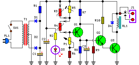 Parts
Parts
- P1 = 1K Linear Potentiometer
- R1 = 10R-1/4W Resistor
- R2 = 1K-1/4W Resistor
- R3 = 3K3 @ 20°C n.t.c. Thermistor (see Notes)
- R4 = 2K2 @ 20°C n.t.c. Thermistor (see Notes)
- R5 = 10K-1/2W Trimmer Cermet
- R6 = 3K3-1/4W Resistor
- R7 = 4K7-1/4W Resistors
- R8 = 470K-1/4W Resistor
- R9 = 4K7-1/4W Resistors
- R10 = 10K-1/4W Resistor
- C1 = 470µF-25V Electrolytic Capacitors
- C2 = 470µF-25V Electrolytic Capacitors
- C3 = 1µF-63V Electrolytic Capacitor
- D1 = 1N4002 - 100V 1A Diodes
- D2 = 1N4002 - 100V 1A Diodes
- D4 = 1N4002 - 100V 1A Diodes
- D3 = LED Red 3 or 5mm.
- Q1 = BC557 - 45V 100mA PNP Transistor
- Q2 = BC547 - 45V 100mA NPN Transistor
- Q3 = BC337 - 45V 800mA NPN Transistor
- J1 = Two ways output socket
- T1 = 220V Primary, 12 + 12V Secondary 3VA Mains transformer
- PL1 = Male Mains plug &cable
- SW1 = SPST Mains Switch
- RL1 = Relay with SPDT 2A @ 220V switch Coil Voltage 12V. Coil resistance 200-300 Ohm
When Q1 Base to ground voltage is less than half voltage supply (set by R7 & R9), a voltage is generated across R8 and the driver transistors Q2 & Q3 switch-on the Relay. When Q1 Base to ground voltage is more than half voltage supply, caused when one of the n.t.c. Thermistors lowers its value due to an increase in temperature, no voltage appears across R8 and the Relay is off. C3 allows a clean switching of the Relay. P1 acts as main temperature control.
Notes:- R3 is the outdoor sensor, R4 the indoor sensor.
- If you are unable to find a 3K3 Thermistor for R3 you can use a 4K7 value instead. The different value can be easily compensated by means of Trimmer R5.
- R5 allows setting the heating system for outdoor temperatures ranging from about +10°C downwards. The higher R5's resistance the hotter the heating system and vice versa.
- The existing boiler thermostat should be set to its maximum value and not bypassed: it is necessary for safety's sake.
- This circuit can be dispensed with its differential feature and converted into a simple precision thermostat omitting R3