


")

Today we are increasingly faced with the use in various applications radio microphones and telephone radioprosvechivaniya devices. Sometimes you want to make sure that the conversation in the apartment or office is not listening.
Usually radiopotassium devices ("bugs") emit a single frequency in the range 30… 500 MHz low power (5 mW). Sometimes such devices are in standby mode: switch on the transmission in the presence of noise in the room (which ensures the efficiency of energy consumption, batteries), or by lifting the handset. The simplest device that can help in the discovery of listening devices, shown in the figure.
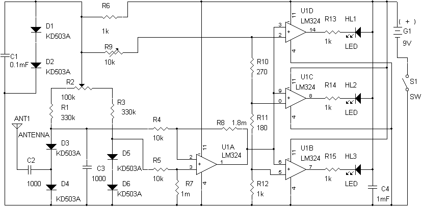
The scheme is broadband bridge detector RF voltage, which covers the frequency range 1… 200 MHz (when using as D01 D06… diodes microwave operating frequency range can be extended) and allows to detect "bugs" at a distance of about 0.5… 1 m (it depends on the transmitter power). It is known that measuring RF voltages with a level less than 0, 5 In hampered by the fact that already at 0.2… 0.3 In all semiconductor diodes when detection becomes ineffective due to the features of their current-voltage characteristics. In this circuit applied the method for measurement of small alternating voltages with the use of the balanced diode-resistor bridge. A small current flowing through the diodes DZ, D4, improves the conditions of detection (increases sensitivity) and allows you to move the lower boundary level of the measured voltage to 20 mV at a uniform amplitude-frequency characteristic. Diodes D5, D6 form the second shoulder of the bridge and ensure the stabilization scheme. On the elements of U1.2… U1. 4 assembled three-level Comparators, the outputs of which are connected the LEDs НL1… НL3. Diodes D1, D2 is applied as a voltage stabilizer 1, 4 In that it is necessary for the sustainable operation of the circuit in a wide range of supply voltages.
The use of the device requires certain skills, as the scheme is quite sensitive and is able to capture close to any radiation, for example the work of the local oscillator of the receiver or TV, and secondary re-radiation conductive surfaces. To facilitate searching for "bug" are used interchangeable antenna pins with different length, which can reduce the sensitivity of the circuit. For example, perhaps the use of removable pins with a length of 400 - 700 - 1200 (mm). When using the device, after its activation, you need a resistor R2 to achieve the illumination of the indicator НL3. This we set the initial level of sensitivity relative to the background. If you move the antenna to the radiation source should begin to glow LEDs НL2 and HL1 with increasing amplitude of the received signal. Adjustment schemes trimming resistor R9 is performed once (during the initial configuration of the device depends on the level of sensitivity thresholds of the Comparators). The scheme keeps working during the change of power from 6 to 10V.
Publication: www.cxem.net