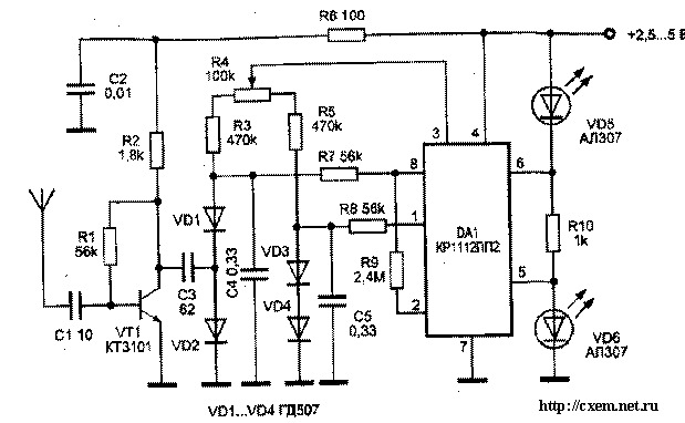
From other designs in this is characterized by small size, small number of parts and, however, a sufficiently high sensitivity. In this field detector used new circuit design. It is well known that the measurement of RF voltages less than 0.5 V, hampered by the fact that when AC voltage is less than 0.2-0.3 In all semiconductor diodes become ineffective. There is, however, the method of measurement of small alternating voltages with the use of the balanced diode-resistor bridge, allowing to measure a voltage of less than 20 mV at a uniform quartermaster to 900 MHz. Schematic diagram devices using this method are shown in the figure.
The basis of this device is DA1 chip type CRP. This chip includes the device determining the balance of the electrical bridge with indication. The chip has a built-in voltage reference.

The signal induced in the antenna, enhanced broadband aperiodic high-frequency amplifier transistor VT1 type CT. Amplified AC high-frequency voltage through the capacitor NW flows into the diode-resistor bridge diodes VD1 - VD4 type GD and resistors R3-R5. From the reference voltage source (pin 3 of chip DA1) through resistors R3-R5 and diodes VD1-VD4 runs a small (about several microamperes) direct current, which improves detection and increases the sensitivity of the detector. In the rectification of the measured AC voltage involves only the diodes VD1 and VD2, and the other two - VD3, VD4 is formed adjacent the shoulder of the bridge, where the initial voltage, balancing the bridge, and at the same time serve for temperature compensation.
All the diodes are matched with possibly more to close the current-voltage characteristics. Capacitor C4 filters out the variable component of the rectified voltage. The resistor R4 serves for precise balancing of the bridge. With good balancing device will respond only to the voltage resulting from the rectification of the measured signal.
Rectified voltage and the voltage balancing bridge, through resistors R7 and R8 are fed to the inputs of the DC amplifier, which is located in the chip DA1. Depending on the condition of bridge balance signal indication is supplied to one of the LEDs or VD5 VD6 - type AL307. Thus, when the balance of the bridge (no signal) led on VD5, and in the presence of the signal (disturbance of balance of the bridge) - led-VD6. As the diodes VD1-VD4, you can use any high-frequency diodes. The LEDs can be of any type.
As the source power supplied to the DC power supply voltage of 2.5-5 V.
Publication: www.cxem.net


