


")

The proposed device allows to fix the transmitter in the range of 27 MHz in a radius of several hundred meters. This can be useful to control the ether in the alarm system, when the radio traffic that occurred near a protected object must be treated as an alarm.
The sensor is a broadband receiver operating in the range of 27 MHz. Bandwidth is the level of 0.7 is 3 MHz. At supply voltage 6 supply current in standby mode -1,1 mA in alarm mode - 3.2 mA. To device you can connect any full-sized antenna which is fed by a cable with a characteristic impedance of 50 Ohms. The use of shortened antennas will reduce the "range". Experience has shown that the sensor is equipped with a full-sized antenna (polvani"), finds work chetyrehbalnoy "portativki" at a distance of 200m.
Diagram of the device shown in Fig. 1. Circuit L2C2 is configured on the middle strip of controlled frequencies. The radio frequency amplifier transistors VT1 and VT2. The amplified signal is removed from the inductor L3 and enters the detector - diode VD1. On transistors VT3 and VT4 assembled a DC amplifier (UPT), which forms a resistor R10 low, if the air is clean, and high - if in the controlled area have a working transmitter. On DD1 chip is assembled generator of disturbing signal.
The sensitivity of a radio receiver depends on the mode of operation of the detector and the SIC, i.e., to what extent compensated cutoff diode VD1 and the transistor VT3. The desired displacement of the working point VT3 is achieved divider R5R6, and the input diode VD1 mode micro-currents the voltage drop across the resistor R4.
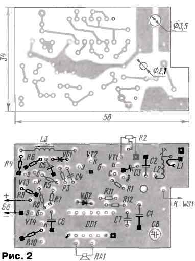
The device is assembled on a printed circuit Board (Fig. 2) of two-sided foil fiberglass with a thickness of 1.5 mm. Foil with side parts is used as the common wire and screen. In places of crossing conductors etched in it circles with a diameter of 1.5…2 mm, and the connections shown with her blackened squares. Squares with a bright dot in the center shows the jumper wire and grounding" by soldering to the foil pins and trimmer. The common wire should be connected and the buildings of the transistors VT1 and VT2.
Coil L1L2 carried on the frame having a thread under MOH carbonyl podstroechnik (Fig. 3). Coil L2 contains 13 turns, she reeled in a number of wire sew-2 0,41. The coil L1 containing three turns, is wound over the cold end of the coil L2 wire PAWSS diameter of from 0.15 to 0.25 mm. Although soldering "vnatyag" conclusions L2 mechanically secures itself to the frame, you can secure the position of the glue is introduced to a support frame.
Resistor R2 - SDR-38A, and the rest - MLT-0,125. Capacitors: C2 - KG or CD, the rest - Km-6 or similar. Choke L3 - D1 -0,1.
Establishing start with a set DC. The antenna is disconnected, trimmer resistor R2 is set on the maximum resistance and dragging the slider, find the position at which the transistor VT4 starts to open. You must set this slider to the transistor VT4, while still closed, was located near the threshold of opening. In this mode, the voltage on its collector will be close to zero. When the receiver input RF signal levels exceeding the threshold, the transistors VT3 and VT4 opens and the voltage at the collector of VT4 will be close to power.
To configure the circuit L2C2 in the middle of the range of controlled frequencies, one can use any suitable high frequency generator, for example, CBS radio operating 50 Ohm antenna equivalent (to not overload the receiver too strong signal). Resonance is determined by a voltmeter or oscilloscope connected to the collector of the transistor VT3. As the convergence of the natural frequencies of the circuit L2C2 with the oscillator frequency constant voltage at the collector of VT3 decreases, reaching a minimum at their coincidence.
Author: Yu. Vinogradov, Moscow; Publication: www.cxem.net