


")

Rechargeable lanterns are often used in emergency situations. But you need to be sure that, long after standing on the shelf, he will not fail in the most inopportune moment. On the brightness of the light the degree of charge of the battery to evaluate it is difficult, periodically check the voltage with a voltmeter extremely uncomfortable. Can to make a device control with led, but the place to install the latest on the lantern are hard to find, and to constantly monitor him not always. Proposed device designed for quick checks of lights railroad track inspectors, makes flashing lamp lamp, if it the battery is dead.
The circuit of the alarm device shown in Fig. 1. When the battery voltage GB1, more voltage stabilizing Zener diode VD1, the transistor VT1 is open, the input EI chip DD1 is set to high logic level. Since this input is shared all elements of the IC, their work is prohibited. The logic level at the outputs of the elements (including at pin 9) low. Transistor VT2 is closed, VT3 opened, the lamp lights EL1.
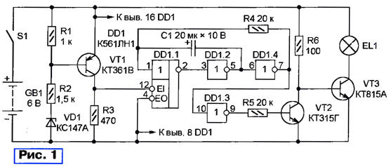
When the voltage of the battery, the transistor VT1 is closed. High logic level at its collector and at the input EI DD1 chip is replaced by a low, translating the elements of the latter in the active state. Starts the generator pulses on the elements DD1.1, DD1.2, DD1.4. Through the element DD1.3 pulses arrive at the base of the transistor VT2, periodically turning on and off the lamp EL1. The flashing frequency depends on the values of resistor R4 and capacitor C1.
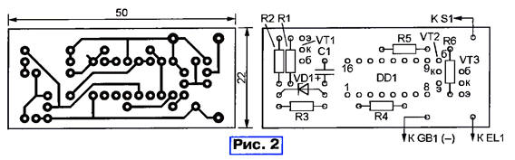
The printed circuit Board of the detector and the arrangement of parts therein shown in Fig. 2. Selecting the resistor R2, it is possible within certain limits to vary the threshold. If a light signal is not enough, you can Supplement it with sound.
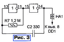
For this purpose two remaining free of chip elements (DD1.5 and DD1.6) collect the acoustic frequency generator according to the scheme shown in Fig. 3. At low the level of the signal EI it starts to operate simultaneously with the first generator, control flashing lamp. Sound frequency depends on the values of resistor R7 and of the capacitor C2. As BF1 suitable piezoelectric sound emitter SN-1, but the best result is obtained with a "Squeaker" from a faulty multimeter.
Author: A. Kalinin, Vologda